
Page 24 - Series-4 Neon-Flex manual
P. 24
24 Ledpro copyright
3. Dynamic Light Wiring
Note:
1. This Neon-Flex must be used in conjunction with DC24V power supply.2.
Always observe proper polarity. Polarity symbols should match on each component.
3. Ensure to add 20% buffer when sizing power supply.
4. Ensure that the power cable carried current is no greater than 80% of its capacity.
5. To minimize the voltage drop and keep light consistency, position power supply nearest to the power feed end of
Neon-Flex and keep the power line as short as possible.
6. Compatible with RGB controller and DMX control.
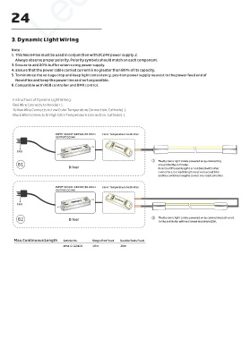
Instructions of Dynamic Light Wiring:
Red Wire Connects to Anode(+).
Yellow Wire Connects to Low Color Temperature Connection, Cathode(-).
Black Wire Connects to High Color Temperature Connection, Cathode(-).
INPUT:AC100~240VAC,50-60Hz Color Temperature Controller
OUTPUT:DC24V
OUT PUT DC+ DC- DC+ DC- DC+ DC- IN PUT DC24V IN PUT DC24V IN PUT DC24V LED
OUT PUT
OUT PUT
DC24V
DC24V
POWER SUPPLY DC24V LED CONTROLLER
POWER SUPPLY
POWER SUPPLY
LED CONTROLLER
LED CONTROLLER
IN PUT
IN PUT OUT PUT OUT PUT OUT PUT W W NC V+ W W NC V+ W W NC V+
IN PUT
AC100-240V
AC100-240V
GND AC100-240V
① The Dynamic light can be powered on by connecting
B1 one end to the controller.
Driver It can be different lengths or combined with other
connectors, but each length must not exceed 10m
and the combined lengths cannot overload controller.
INPUT:AC100~240VAC,50-60Hz Color Temperature Controller
OUTPUT:DC24V
OUT PUT
OUT PUT DC+ DC- DC+ DC- DC+ DC- IN PUT DC24V IN PUT DC24V IN PUT DC24V LED
OUT PUT
DC24V
DC24V
DC24V
POWER SUPPLY
POWER SUPPLY
POWER SUPPLY
LED CONTROLLER
LED CONTROLLER
LED CONTROLLER
IN PUT
IN PUT OUT PUT OUT PUT OUT PUT W W NC V+ W W NC V+ W W NC V+
IN PUT
GND AC100-240V
AC100-240V
AC100-240V
B2 Driver ② The Dynamic light can be powered on by connecting both ends
to the controller within allowed maximum 20m.
Max.Continuous Length Article No. Single End Feed Double Ends Feed
NFS4-D-D24CV 10m 20m