
Page 22 - Series-4 Neon-Flex manual
P. 22
22 Ledpro copyright
Diagram
of
Light
Wiring
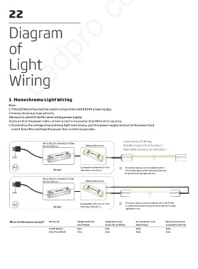
1. Monochrome Light Wiring
Note:
1. This LED Neon-Flex must be used in conjunction with DC24V power supply.
2. Always observe proper polarity.
3. Ensure to add 20% buffer when sizing power supply.
4. Ensure that the power cable carried current is no greater than 80% of its capacity.
5. To minimize the voltage drop and keep light consistency, position power supply nearest to the power feed
end of Neon-Flex and keep the power line as short as possible.
Instructions of Wiring:
INPUT:AC100~240VAC,50-60Hz
OUTPUT:DC24V Dimmer(Optional) Red Wire Connects to Anode(+)
Black Wire Connects to Cathode(-)
OUT PUT DC+ DC- DC+ DC- DC+ DC- IN PUT DC24V IN PUT DC24V IN PUT DC24V LED
OUT PUT
OUT PUT
DC24V
DC24V
W W NC V+
W W NC V+
POWER SUPPLY DC24V
POWER SUPPLY
POWER SUPPLY
LED CONTROLLER
LED CONTROLLER
LED CONTROLLER
IN PUT
IN PUT OUT PUT OUT PUT OUT PUT W W NC V+
IN PUT
GND AC100-240V
AC100-240V
AC100-240V
A1 (Compatible with most 0~10V ① The power supply can drive one length or
Driver dimming controllers.) different lengths within allowed maximum
length by feeding light one end.
INPUT:AC100~240VAC,50-60Hz
OUTPUT:DC24V Dimmer(Optional)
OUT PUT
OUT PUT DC+ DC- DC+ DC- DC+ DC- IN PUT DC24V IN PUT DC24V IN PUT DC24V LED
OUT PUT
DC24V
DC24V
POWER SUPPLY DC24V LED CONTROLLER
POWER SUPPLY
POWER SUPPLY
W W NC V+
W W NC V+
LED CONTROLLER
LED CONTROLLER
IN PUT
IN PUT OUT PUT OUT PUT OUT PUT W W NC V+
IN PUT
GND AC100-240V
AC100-240V
AC100-240V
A2 (Compatible with most 0~10V ② The power supply can drive one length or different
Driver dimming controllers.) lengths within allowed maximum length by feeding
light both ends.
Max.Continuous Length Article No. Single End Feed Single End Feed Double Ends Feed Double Ends Feed
Red/Amber Green/Blue/White Red/Amber Green/Blue/White
NFS4B-D24CC 15m 10m 30m 20m
NFS4-Pro-D24CC 15m 10m 30m 20m