Follow every contour
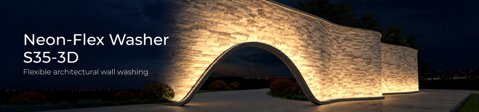
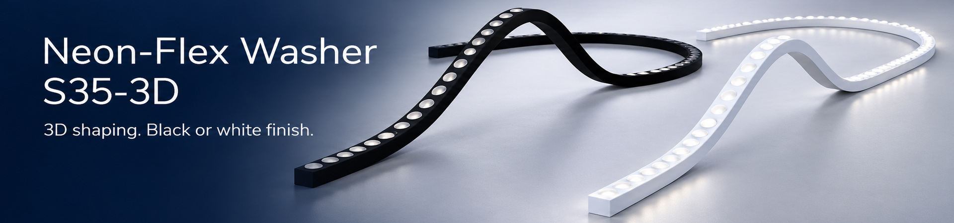
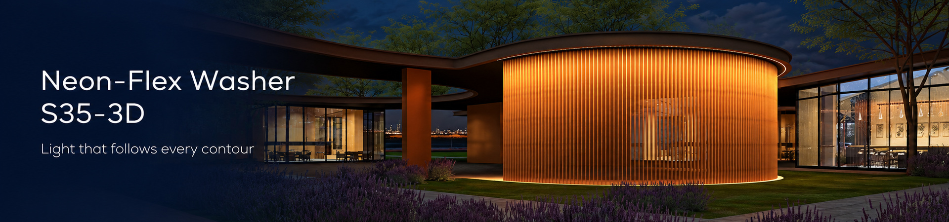
Horizontal and vertical bending allow the lightline to follow curved walls and three-dimensional forms.
Horizontaal en verticaal buigbaar voor gebogen gevels en driedimensionale vormen.


LEDPRO · Architectural lighting
A highly flexible, high-output LED wall washer that follows architectural contours. Shape light in three dimensions, with controlled optical distributions and a choice of mounting profiles for straight, curved and adjustable installations.
Een zeer flexibele LED wallwasher met hoge lichtopbrengst, die de contouren van de architectuur volgt. Driedimensionaal vormbaar, met gerichte optieken en montageprofielen voor rechte, gebogen en verstelbare toepassingen.
Horizontal and vertical bending allow the lightline to follow curved walls and three-dimensional forms.
Horizontaal en verticaal buigbaar voor gebogen gevels en driedimensionale vormen.
Five optical distributions for white light; 20° × 40° optics for RGB and RGBW.
Vijf optieken voor wit licht; 20° × 40° voor RGB en RGBW.
Rigid, bendable and flexible profiles, glare shields and adjustable mounting brackets.
Rechte, buigbare en flexibele profielen, afscherming en verstelbare montagebeugels.
Designed for architectural façades, stone walls, curved surfaces and landscape features. Integrated lenses and silicone housing combine a compact appearance with directional wall washing.
The series offers static white, tunable white, RGB and RGBW, plus DMX and SPI variants for pixel control. Choose black or white finishes to suit the installation.
UV- and heat-resistant lens and silicone construction. Consistent lens pitch is maintained at the joints.
| Parameter | Specification |
|---|---|
| Working voltage | 24 V DC |
| Rated power | 24 W/m |
| LED quantity | 28 LEDs/m |
| Cross-section | 35 × 25 mm |
| Protection | IP68; not suitable for underwater use |
| Impact rating | IK10; IK08 in bendable H36 profiles |
| CRI | 80 (white-light variants) |
| Weight | 1,100 g/m |
| Working temperature | -40 to +55 °C |
| Storage temperature | -40 to +60 °C |
| Installation temperature | > -40 °C |
| Max. mounting surface temperature | 85 °C |
| Standard piece length | 250–2,000 mm, in 250 mm increments |
| Maximum connected length | 5,000 mm in series |
| Nominal load at 5 m | 120 W / 5 A at 24 V (calculated) |
| Lightline minimum bend diameter | HB Ø800 mm / VB Ø400 mm |
| Finishes | Black base / black light surface; white base / white light surface |
* IP68 does not mean this product is suitable for underwater use. IK rating depends on the selected mounting profile.
HB: minimum diameter Ø800 mm (radius 400 mm). VB: minimum diameter Ø400 mm (radius 200 mm). Piece length: 250–2,000 mm in 250 mm steps; max. 5,000 mm in series.
IP68 silicone injection-moulded connections. Dimensions are shown in mm. Connector drawing tolerance ±0.5 mm.
| Control | Light colour | Options | Lens options | Power | Pixel density |
|---|---|---|---|---|---|
| Standard | Static white | 2700 / 3000 / 3500 / 4000 / 5700 K | 12° / 25° / 15° × 25° / 15° × 40° / 15° × 60° | 24 W/m | — |
| Standard | Tunable white | 2700–6500 K | 12° / 25° / 15° × 25° / 15° × 40° / 15° × 60° | 24 W/m | — |
| Standard | RGB | Red / green / blue | 20° × 40° | 24 W/m | — |
| Standard | RGBW | RGB + 3000 K white | 20° × 40° | 24 W/m | — |
| DMX (UCS512CN) | Static white | 2700 / 3000 / 3500 / 4000 / 5700 K | 12° / 25° / 15° × 25° / 15° × 40° / 15° × 60° | 24 W/m | 4 pixels/m |
| DMX (UCS512CN) | Tunable white | 2700–6500 K | 12° / 25° / 15° × 25° / 15° × 40° / 15° × 60° | 24 W/m | 4 pixels/m |
| DMX (UCS512CN) | RGB | Red / green / blue | 20° × 40° | 24 W/m | 4 pixels/m |
| DMX (UCS512CN) | RGBW | RGB + 3000 K white | 20° × 40° | 24 W/m | 4 pixels/m |
| SPI (UCS2903) | Static white | 2700 / 3000 / 3500 / 4000 / 5700 K | 12° / 25° / 15° × 25° / 15° × 40° / 15° × 60° | 24 W/m | 4 pixels/m |
| SPI (UCS2903) | Tunable white | 2700–6500 K | 12° / 25° / 15° × 25° / 15° × 40° / 15° × 60° | 24 W/m | 4 pixels/m |
| SPI (UCS2903) | RGB | Red / green / blue | 20° × 40° | 24 W/m | 4 pixels/m |
| SPI (UCS2903) | RGBW | RGB + 3000 K white | 20° × 40° | 24 W/m | 4 pixels/m |
All configurations: 24 V DC, 28 LEDs/m, 250 mm minimum length increment, black or white finish. The control variant must match the selected controller.
Values below are finished-product lumen output per metre. The “>” values and the differences between black and white finishes are preserved from the specification.
| CCT / Black finish | 12° | 25° | 15° × 25° | 15° × 40° | 15° × 60° |
|---|---|---|---|---|---|
| 2700 K | >1350 | >1400 | >1500 | >1350 | >1150 |
| 3000 K | >1450 | >1500 | >1600 | >1500 | >1300 |
| 3500 K | >1450 | >1500 | >1600 | >1500 | >1300 |
| 4000 K | >1550 | >1600 | >1700 | >1600 | >1400 |
| 5700 K | >1450 | >1600 | >1700 | >1600 | >1400 |
| CCT / White finish | 12° | 25° | 15° × 25° | 15° × 40° | 15° × 60° |
|---|---|---|---|---|---|
| 2700 K | >1600 | >1700 | >1750 | >1650 | >1450 |
| 3000 K | >2000 | >1800 | >1900 | >1800 | >1800 |
| 3500 K | >2000 | >1800 | >1900 | >1800 | >1800 |
| 4000 K | >1850 | >1950 | >2000 | >1900 | >1700 |
| 5700 K | >1750 | >1950 | >1950 | >1700 | >1900 |
The specification gives identical values for the DMX and SPI variants.
| CCT / Black finish | 12° | 25° | 15° × 25° | 15° × 40° | 15° × 60° |
|---|---|---|---|---|---|
| 2700 K | >1200 | >1250 | >1250 | >1200 | >1050 |
| 3000 K | >1450 | >1350 | >1350 | >1300 | >1300 |
| 3500 K | >1450 | >1350 | >1350 | >1300 | >1300 |
| 4000 K | >1450 | >1500 | >1550 | >1500 | >1300 |
| 5700 K | >1350 | >1500 | >1500 | >1300 | >1450 |
| CCT / White finish | 12° | 25° | 15° × 25° | 15° × 40° | 15° × 60° |
|---|---|---|---|---|---|
| 2700 K | >1450 | >1550 | >1600 | >1500 | >1450 |
| 3000 K | >1800 | >1650 | >1700 | >1600 | >1600 |
| 3500 K | >1800 | >1650 | >1700 | >1600 | >1600 |
| 4000 K | >1800 | >1850 | >1900 | >1800 | >1600 |
| 5700 K | >1700 | >1850 | >1850 | >1800 | >1800 |
| Lens | Black 2700 K | Black 6500 K | White 2700 K | White 6500 K |
|---|---|---|---|---|
| 12° | >760 | >800 | >880 | >930 |
| 25° | >730 | >800 | >910 | >1000 |
| 15° × 25° | >840 | >890 | >960 | >1020 |
| 15° × 40° | >780 | >840 | >920 | >980 |
| 15° × 60° | >680 | >720 | >820 | >850 |
| Lens | Black 2700 K | Black 6500 K | White 2700 K | White 6500 K |
|---|---|---|---|---|
| 12° | >640 | >670 | >800 | >830 |
| 25° | >650 | >720 | >820 | >900 |
| 15° × 25° | >700 | >740 | >870 | >920 |
| 15° × 40° | >670 | >700 | >830 | >880 |
| 15° × 60° | >590 | >610 | >740 | >770 |
Warm and cool channel values are listed separately; they are not a statement of combined output.
| Variant / finish | Red | Green | Blue | RGB combined | White 3000 K |
|---|---|---|---|---|---|
| RGB / Black | >125 | >280 | >60 | >465 | — |
| RGB / White | >150 | >340 | >75 | >565 | — |
| RGBW / Black | >100 | >225 | >60 | >385 | >290 |
| RGBW / White | >115 | >265 | >75 | >455 | >350 |
| Variant / finish | Red | Green | Blue | RGB combined | White 3000 K |
|---|---|---|---|---|---|
| RGB / Black | >115 | >270 | >30 | >415 | — |
| RGB / White | >145 | >335 | >80 | >560 | — |
| RGBW / Black | >80 | >230 | >70 | >380 | >315 |
| RGBW / White | >100 | >275 | >85 | >460 | >380 |
RGBW white channel: 3000 K, CRI 80. Red 619–624 nm; green 520–535 nm; blue 460–475 nm.
| Nominal CCT | Specified CCT / tolerance |
|---|---|
| 2700 K | 2725 ±115 K |
| 3000 K | 3045 ±140 K |
| 3500 K | 3465 ±170 K |
| 4000 K | 3985 ±225 K |
| 5700 K | 5665 ±355 K |
| Tunable white, warm endpoint | 2725 ±145 K |
| Tunable white, cool endpoint | 6532 ±510 K |
| RGBW white channel | 3045 ±175 K |
Choose the mounting system to suit the required bend direction, installation depth and aiming angle.
Dimensioned section sketches below are schematic. Profile and accessory designations follow the supplied specification; no new order codes have been assigned. Click a sketch to enlarge.
| Section sketch | Profile / accessory | Dimensions | Available lengths | Description |
|---|---|---|---|---|
| Serrated aluminium profile H50 H50 | 41 × 50 mm | 50, 500, 1,000, 2,000 mm | With cable raceway. IK10. | |
| Serrated aluminium profile H36 H36 | 41 × 36 mm | 50, 500, 1,000, 2,000 mm | Rigid mounting profile. IK10. | |
| Bendable serrated aluminium profile H36 (HB) H36-HB | 41 × 36 mm | 1,000 mm | Min. bend diameter Ø1,200 mm. Installed assembly IK08. | |
| Bendable serrated aluminium profile H36 (VB) H36-VB | 41 × 36 mm | 1,000 mm | Min. bend diameter Ø2,000 mm. Installed assembly IK08. | |
| Pivot-lift serrated aluminium profile Pivot-lift | 41 × 45 mm | 500, 1,000 mm | Max. adjustable angle 90°. IK10. | |
| Flexible profile, surface / recessed installation Anole3525 / Anole3525-IN | 41.5 × 34 mm | 200, 500, 1,000 mm | Black or white. HB Ø800 mm / VB Ø400 mm. IK08. Dimension tolerance ±0.5 mm. | |
| Adjustable mounting bracket Adjustable bracket | 41 × 53.9 mm | — | 304 stainless steel; 180° rotation. Rotation is restricted when used with a bendable profile. | |
| Bendable aluminium glare shield Glare shield (HB) | 76 mm overall height; 40 mm shield extension | 1,000, 2,000 mm | HB min. bend diameter Ø1,200 mm. Not suitable for the vertical bending profile. | |
| Dual-adjustable mounting bracket Dual-adjustable bracket | 40 × 73.4 mm; 78.8 mm body length | — | 304 stainless steel. Adjustable wall distance 80–120 mm; 180° rotation. Works with the listed profiles. |
Aluminium profile dimensions: tolerance ±0.3 mm. Flexible profile: ±0.5 mm. The glare-shield sketch shows the overall section schematically; use the supplied installation dimensions for fabrication.
The lightline uses IP68 silicone injection-moulded connections. Optional male/female connectors are approximately 50 × 20 mm. An anti-wicking ferrule is part of the cable assembly and must remain in place; removing it can cause water ingress.
Factory-moulded connections are part of the lightline assembly and are not presented as loose endcaps.
Select the profile for the required bending direction. Do not bend below the minimum diameter of either the lightline or its profile. Check the power supply and the maximum connected length before installation.
Cut the mounting profile to length with a suitable saw. Remove burrs and sharp edges. At a joint, leave approximately 5 mm between profiles and keep the sections aligned vertically and horizontally. Misalignment can damage the lightline and PCB.
Mark and drill the fixing holes appropriate for the mounting surface. Keep the profile interior clear of debris; sharp fragments can damage the silicone and cause water ingress. With adjustable mounting brackets, use 2–3 brackets per metre as recommended in the installation instructions.
Fit the profile into the shield slots and push it forward. Shape the glare shield together with the horizontal bendable profile. Minimum bend diameter Ø1,200 mm; do not use the shield with the vertical bending profile.
Press the lightline into the profile progressively. Keep the insertion angle between the lightline and profile at 30° or less. With H36 profiles, leave about 20 mm of the lightline outside the profile at the end. With H50 profiles, the lightline end can align with the profile end.
Do not pull or load the ends of the lightline. Avoid scratches to the cable sheath and keep the anti-wicking ferrule intact. Align the red marks on the male/female connectors, insert, then tighten clockwise. Use a professional waterproof junction box or suitable waterproof connector for cable treatment; wrapping the cable in waterproof tape alone is not sufficient.
After completing the electrical connections, test the lighting and set the required aiming angle. Observe the mounting bracket limits and the selected profile’s bending limits.
Lift the lightline carefully from the bottom with a screwdriver as described in the installation instructions. Keep the angle between the lightline and profile at 30° or less during removal.
Original installation drawings. Click any drawing to enlarge. Dimensions are in mm.
An Environmental Product Declaration (EPD) summarises the environmental impacts assessed over a product’s life cycle: raw material extraction, manufacturing, transport, use and end of life. It can support comparison and evaluation of construction products.
For product-specific environmental documentation, contact sales@ledpro.nl.
Contact LEDPRO for the configuration, mounting system and project-specific power supply.
| Cookie | Duration | Description |
|---|---|---|
| cookielawinfo-checkbox-analytics | 11 months | This cookie is set by GDPR Cookie Consent plugin. The cookie is used to store the user consent for the cookies in the category "Analytics". |
| cookielawinfo-checkbox-functional | 11 months | The cookie is set by GDPR cookie consent to record the user consent for the cookies in the category "Functional". |
| cookielawinfo-checkbox-necessary | 11 months | This cookie is set by GDPR Cookie Consent plugin. The cookies is used to store the user consent for the cookies in the category "Necessary". |
| cookielawinfo-checkbox-others | 11 months | This cookie is set by GDPR Cookie Consent plugin. The cookie is used to store the user consent for the cookies in the category "Other. |
| cookielawinfo-checkbox-performance | 11 months | This cookie is set by GDPR Cookie Consent plugin. The cookie is used to store the user consent for the cookies in the category "Performance". |
| viewed_cookie_policy | 11 months | The cookie is set by the GDPR Cookie Consent plugin and is used to store whether or not user has consented to the use of cookies. It does not store any personal data. |