


LEDPRO · Flexible linear lighting
Download PDF ↗Neon-Flex Series-4N
RGB / RGBW · Voltage · 24V
Continuous colour-changing light in RGB or RGBW. Choose voltage-controlled colour mixing, with a dedicated white channel on the RGBW version.
Doorlopende kleurveranderende verlichting in RGB of RGBW. Spanningsgestuurde kleurmenging, met een apart witlichtkanaal bij de RGBW-uitvoering.
Key advantages
Uniform light
A continuous light line without visible LED dots.
Een doorlopende lichtlijn zonder zichtbare LED-punten.
RGB or RGBW
RGB colour mixing, or RGB with an additional dedicated white channel.
RGB-kleurmenging, of RGB met een aanvullend afzonderlijk witlichtkanaal.
Installation options
Connection and mounting options for different installation layouts.
Aansluitingen en montageprofielen voor verschillende installaties.
Product overview
Continuous colour-changing light in RGB or RGBW. Choose voltage-controlled colour mixing, with a dedicated white channel on the RGBW version. The technical sheets below show the available connection and mounting options.
Technical specifications
| Parameter | Specification |
|---|---|
| Working voltage | 24V DC |
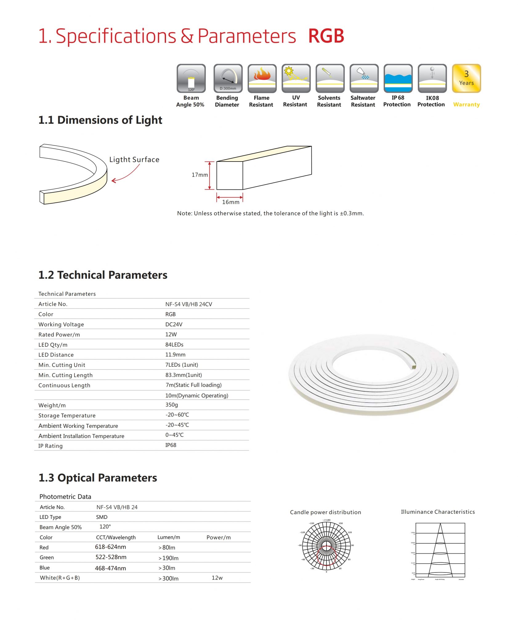
| Dimensions | 16 × 17 mm · tolerance ±0.3 mm |
| Construction | UV- and flame-resistant PVC |
| LED quantity / spacing | 84 LEDs/m · 11.9 mm |
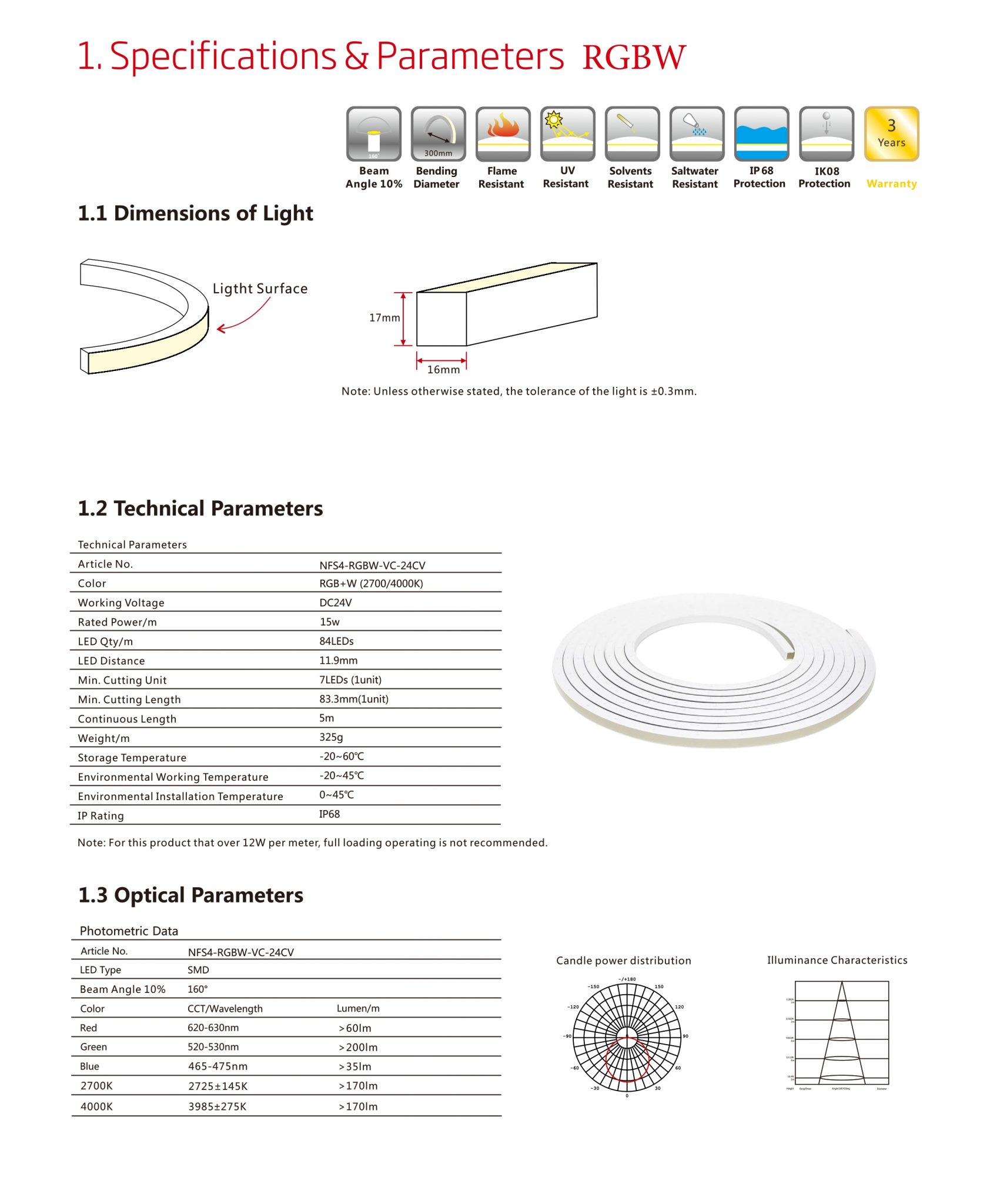
| Beam angle | RGB: 120° at 50% · RGBW: 160° at 10% |
| Minimum bend | Ø 300 mm · radius 150 mm |
| IP rating | IP68 light body; assembly rating depends on connectors |
| Storage temperature | −20 to +60 °C |
| Operating ambient temperature | −20 to +45 °C |
| Installation ambient temperature | 0 to +45 °C |
| Weight | RGB: 350 g/m · RGBW: 325 g/m |
| Warranty | 3 years |
*The complete installation takes the IP rating of its assembled components. Match the connectors to the required protection.
Available configurations
| Version | Power / m | Cutting unit | Cut interval | Single-end length |
|---|---|---|---|---|
| RGB | 12 W | 7 LEDs | 83.3 mm | 10 m dynamic · 7 m static full load |
| RGBW · 2700K / 4000K | 15 W | 7 LEDs | 83.3 mm | 5 m |
The RGBW datasheet advises against continuous full-load operation above 12 W/m.
Dimensions & bend radius
Dimensions · 16 × 17 mm
Minimum bend · Ø 300 mm
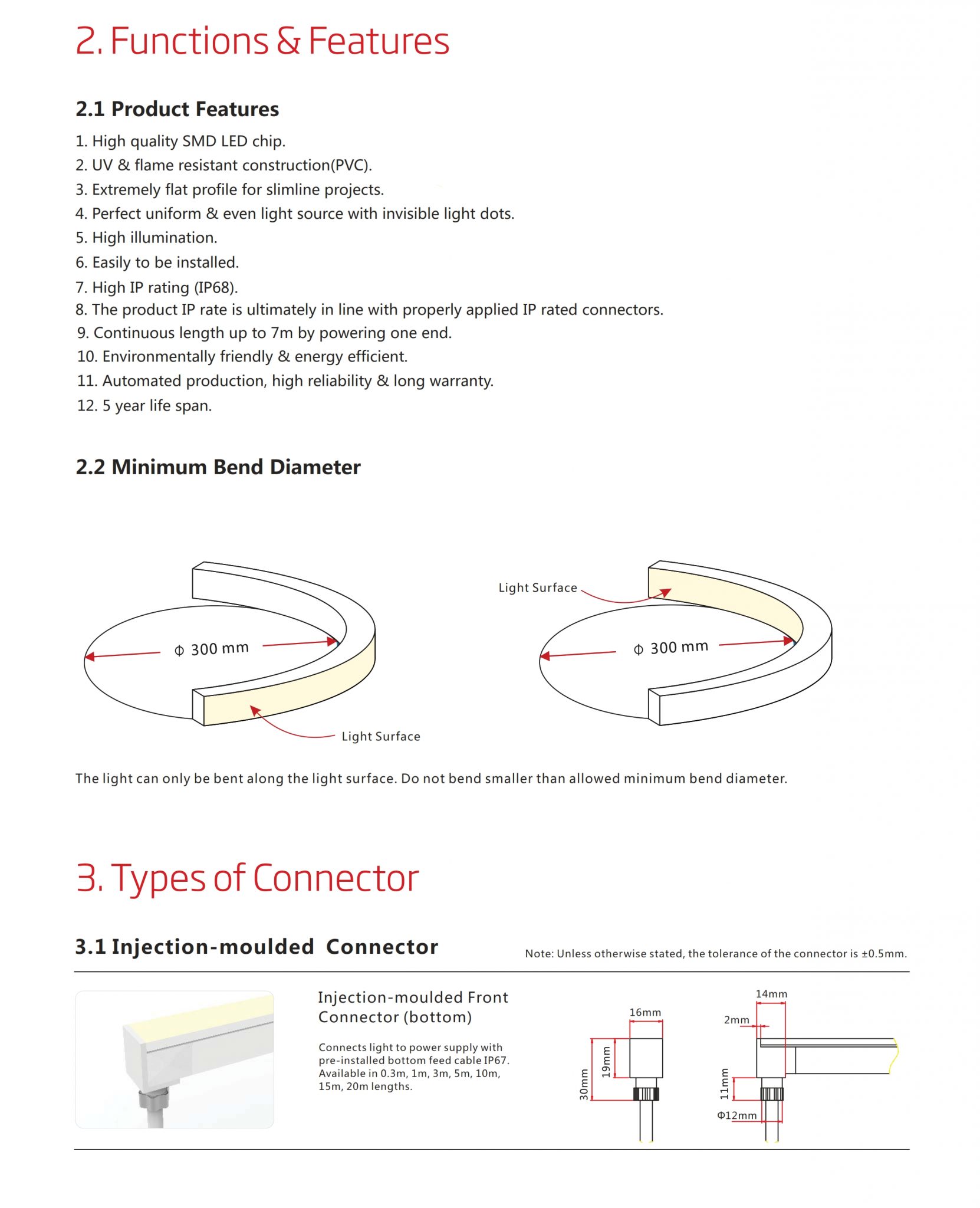
Bend only in the indicated direction. Minimum radius: 150 mm. Click a technical image to open the complete sheet.
Light output
RGB
| Colour | Wavelength | Lumen / m |
|---|---|---|
| Red | 618–624 nm | >80 lm |
| Green | 522–528 nm | >190 lm |
| Blue | 468–474 nm | >30 lm |
| White (R+G+B) | — | >300 lm |
RGBW
| Colour | Wavelength / CCT | Lumen / m |
|---|---|---|
| Red | 620–630 nm | >60 lm |
| Green | 520–530 nm | >200 lm |
| Blue | 465–475 nm | >35 lm |
| 2700K | 2725 ±145K | >170 lm |
| 4000K | 3985 ±275K | >170 lm |
Optical data and specifications — full technical drawing
RGBW optical data and specifications — full technical drawing
Connections & accessories
Injection-moulded connectors · IP67
| Image | Connection | Specification |
|---|---|---|
| Bottom feed | Pre-installed bottom cable · IP67 |
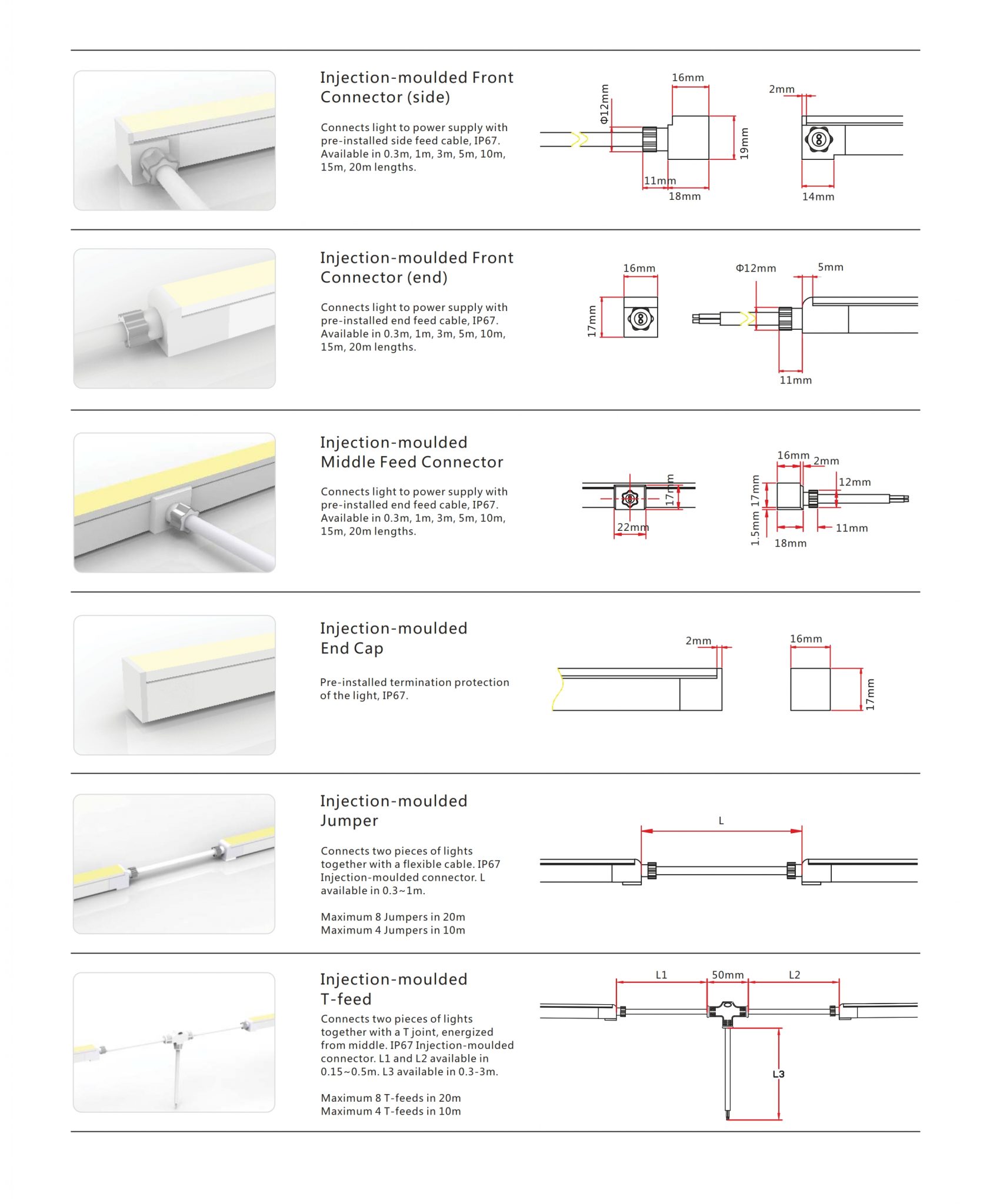 | Side feed | Pre-installed side cable · IP67 |
| End feed | Pre-installed end cable · IP67 |
| Middle feed | Pre-installed middle cable · IP67 |
| End cap | Factory-moulded termination · IP67 |
| Jumper | Injection-moulded link · IP67 |
| T-feed | Injection-moulded branch · IP67 |
Bending and bottom-feed connection — full technical drawing
Injection-moulded connectors — full technical drawing
Dual injection-moulded connectors · IP68
| Image | Connection | Specification |
|---|---|---|
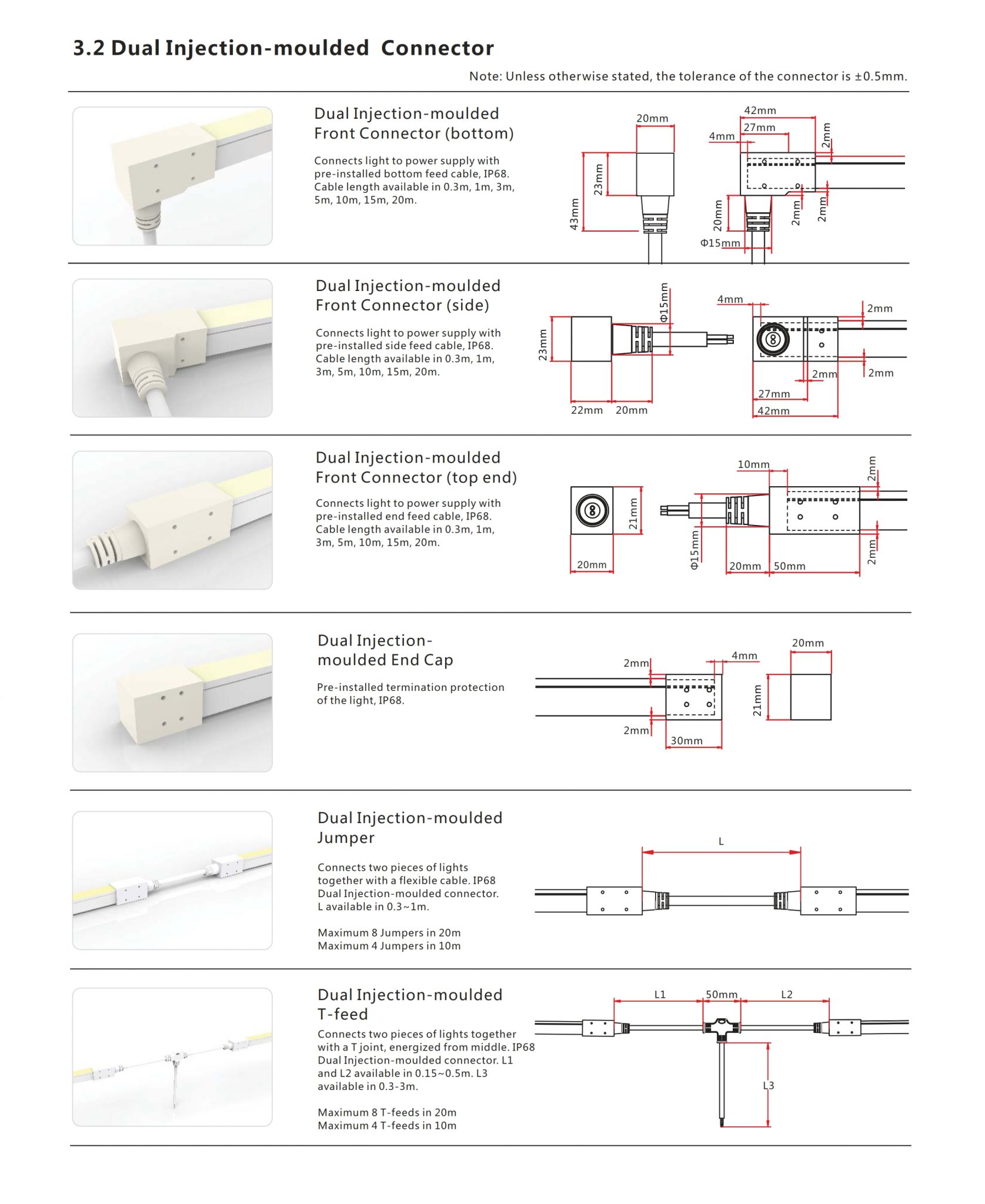 | Bottom feed | Factory-moulded bottom cable · IP68 |
| Side feed | Factory-moulded side cable · IP68 |
| End feed | Factory-moulded end cable · IP68 |
| End cap | Factory-moulded termination · IP68 |
| Jumper | Factory-moulded link · IP68 |
| T-feed | Factory-moulded branch · IP68 |
Dual injection-moulded connectors — full technical drawing
Cable accessories
| Image | Accessory | Specification |
|---|---|---|
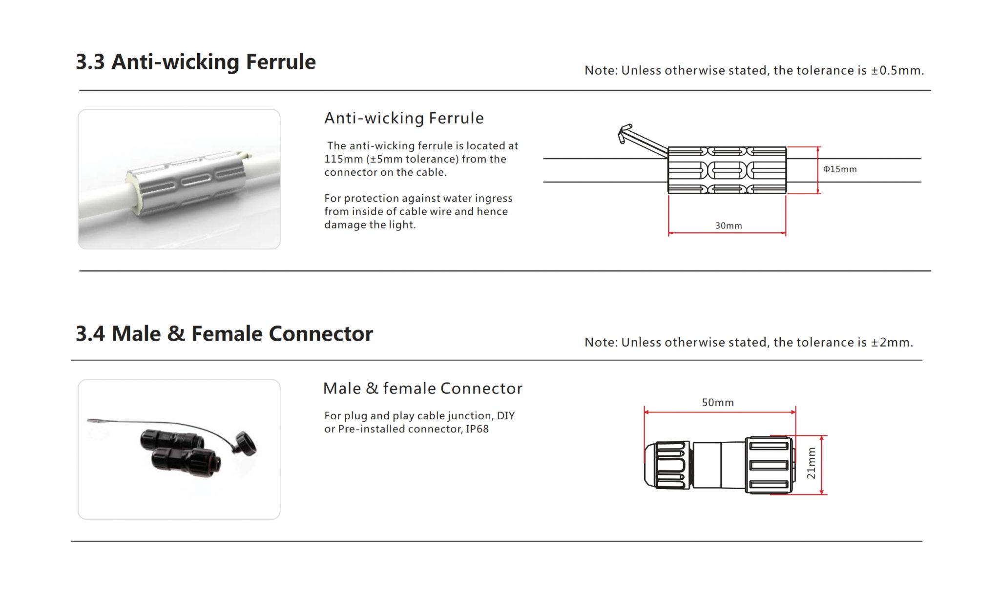 | Anti-wicking ferrule | Helps prevent moisture migration through the cable. |
| Male & female connector | Plug-and-play cable joint · IP68 |
Ferrule and cable connector — full technical drawing
Full drawings specify dimensions, cable lengths, components and connector protection. Select the feed direction and left/right version for the installation.
Mounting profiles
| Image | Profile / version | Dimensions & mounting |
|---|---|---|
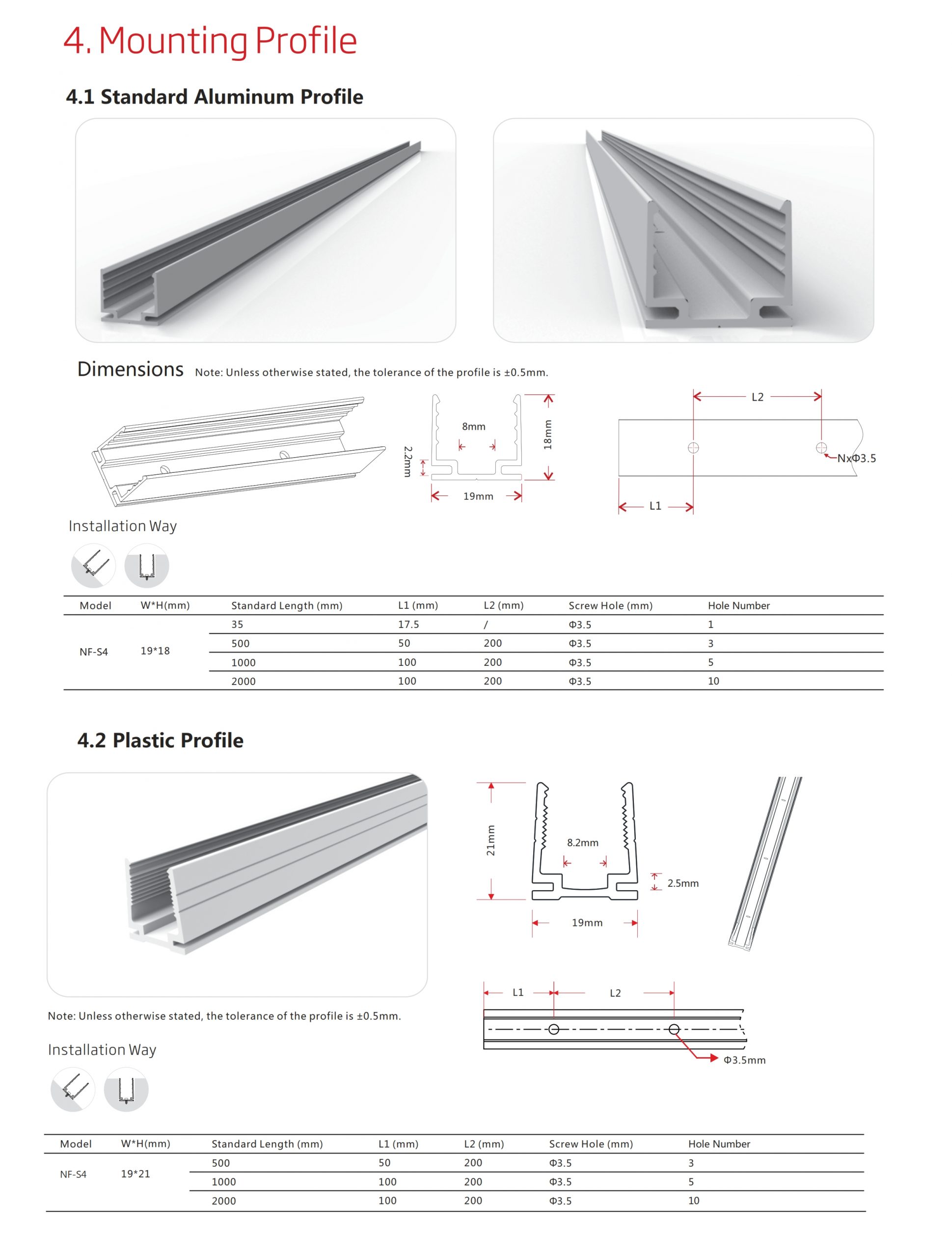 | Standard aluminium | Dimensions, lengths and mounting details in the full drawing. |
| Plastic | Dimensions, lengths and mounting details in the full drawing. |
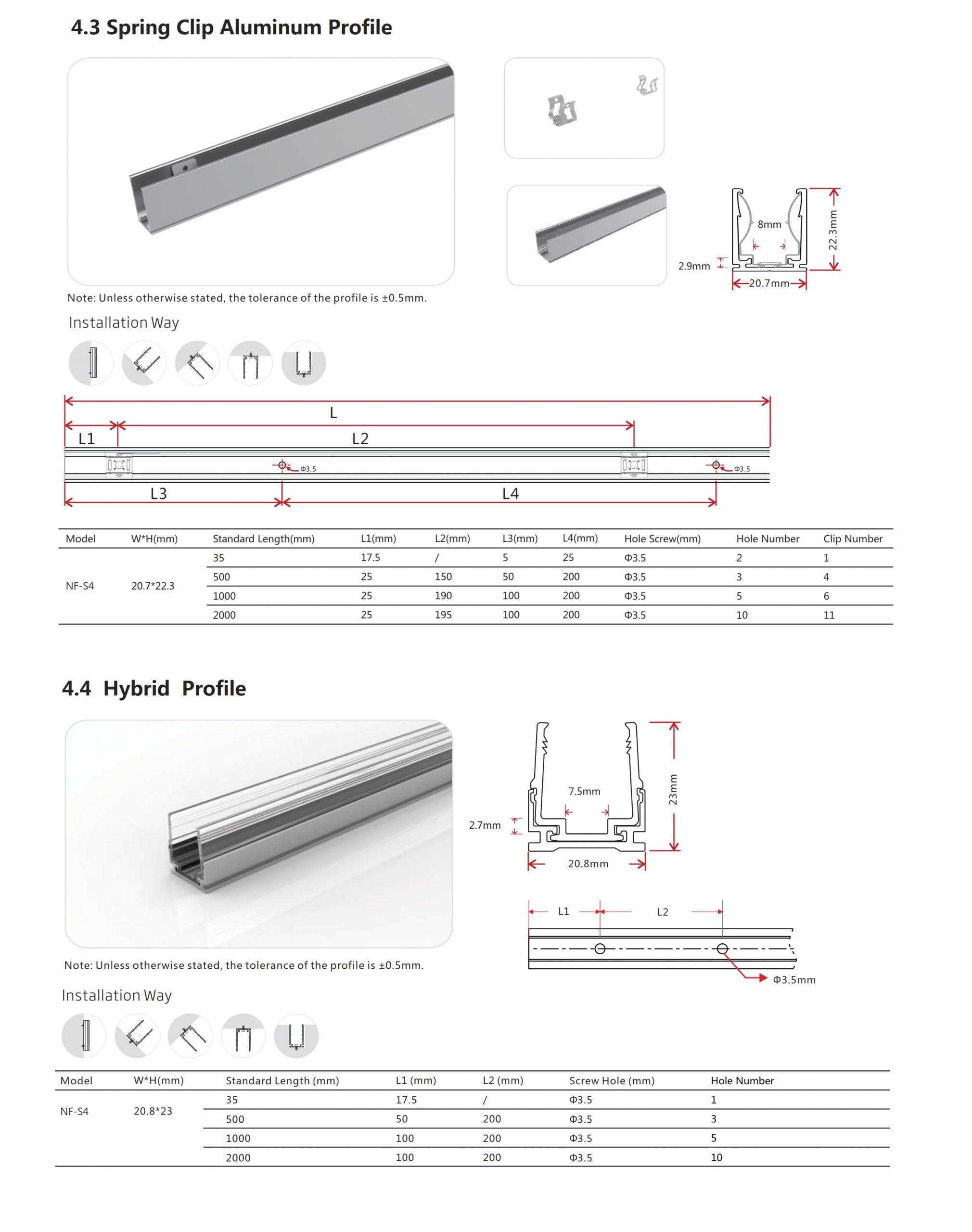 | Spring clip aluminium | Dimensions, lengths and mounting details in the full drawing. |
| Hybrid | Dimensions, lengths and mounting details in the full drawing. |
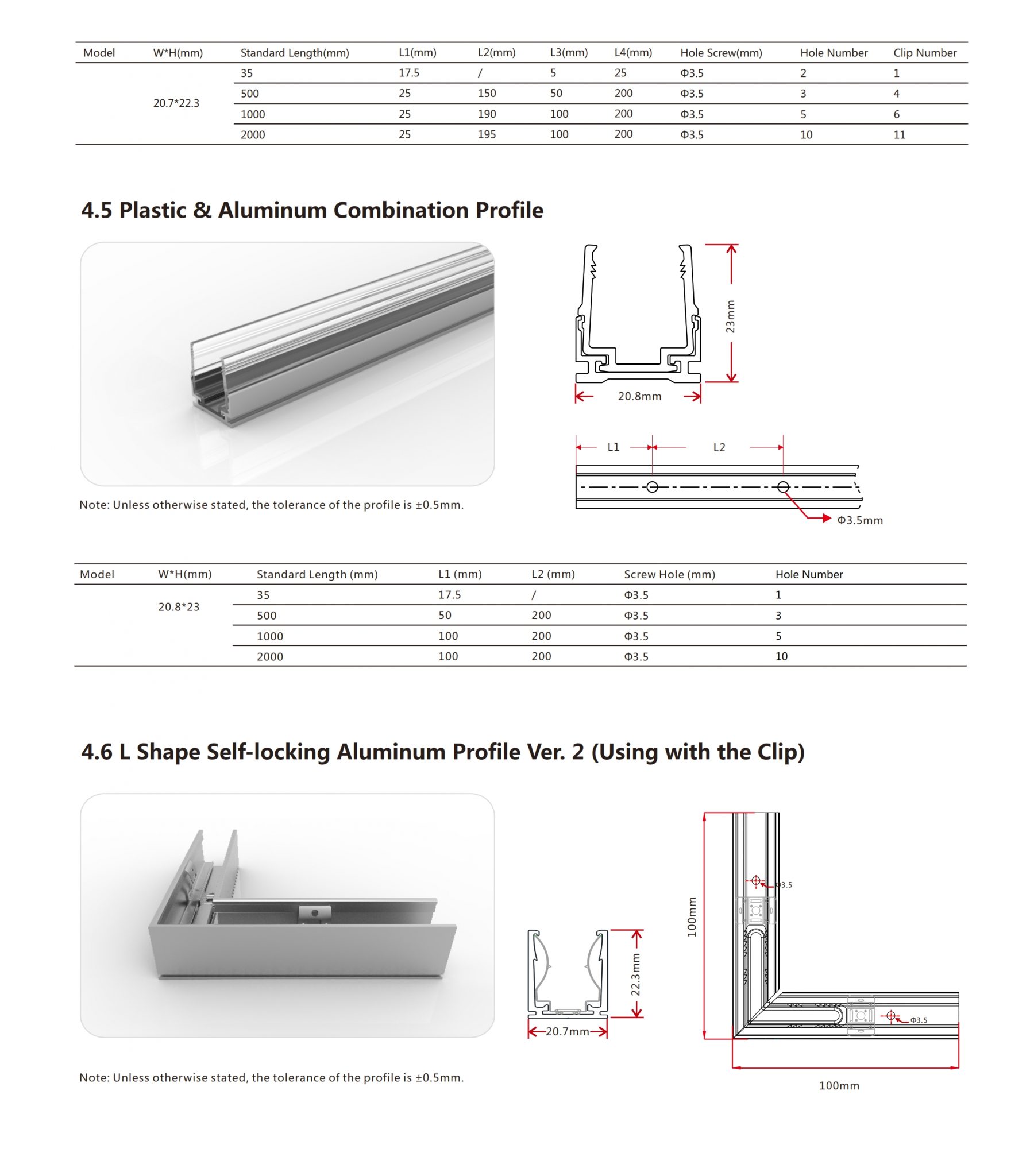 | Plastic & aluminium combination | Dimensions, lengths and mounting details in the full drawing. |
| L-shaped self-locking | Dimensions, lengths and mounting details in the full drawing. |
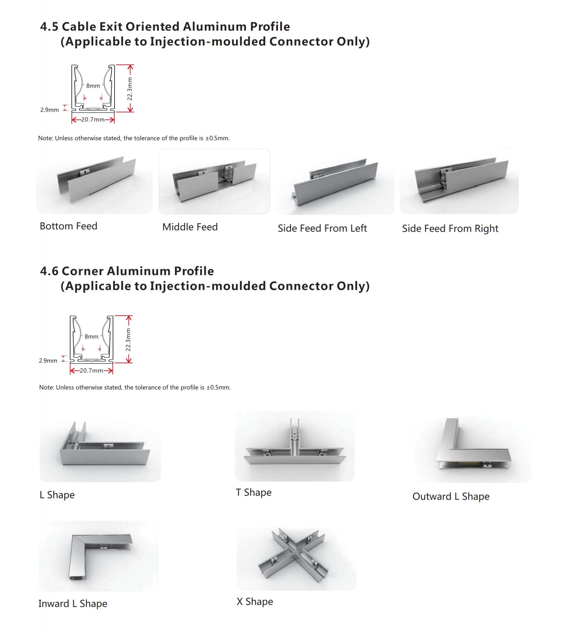 | Cable-exit oriented aluminium | Dimensions, lengths and mounting details in the full drawing. |
| Corner aluminium | Dimensions, lengths and mounting details in the full drawing. |
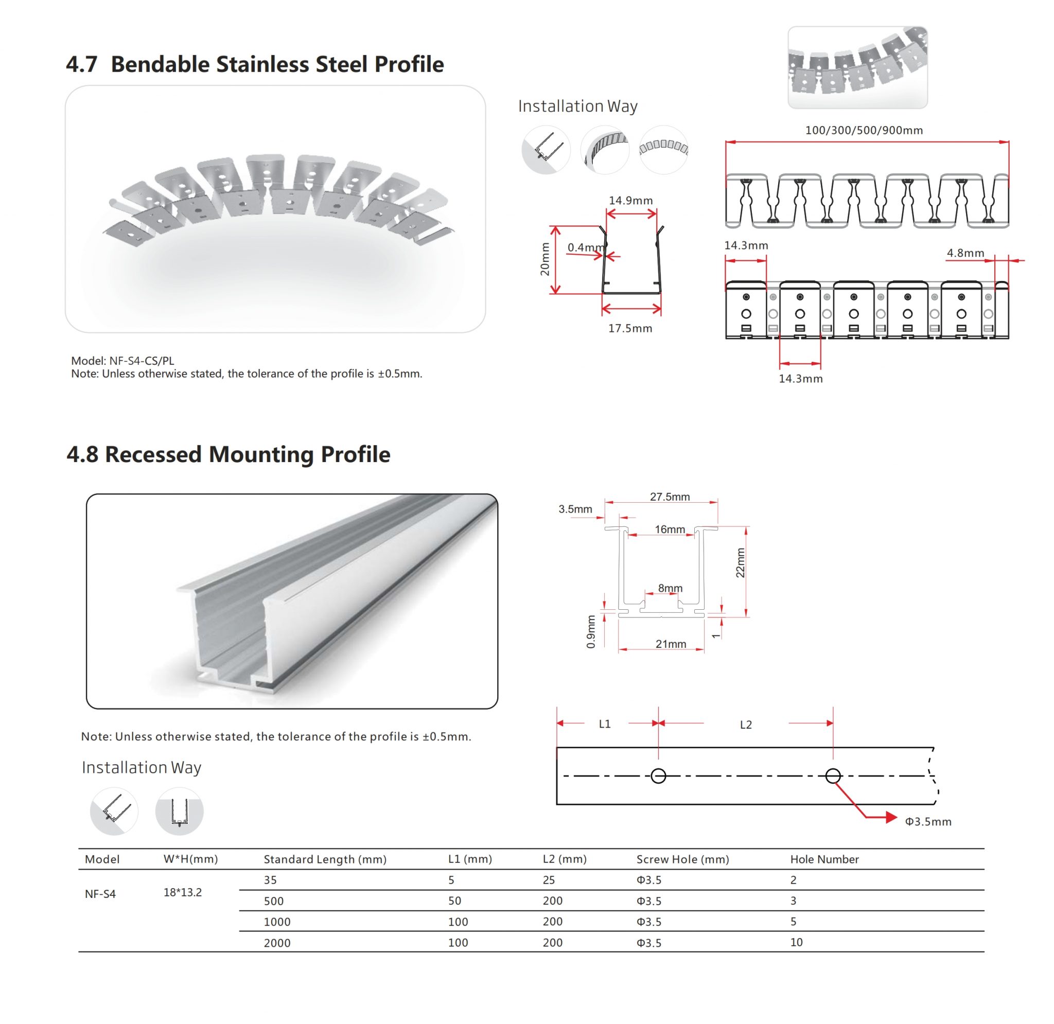 | Bendable stainless steel | Dimensions, lengths and mounting details in the full drawing. |
| Recessed mounting | Dimensions, lengths and mounting details in the full drawing. |
Mounting profiles · sheet 1 — full technical drawing
Mounting profiles · sheet 2 — full technical drawing
Mounting profiles · sheet 3 — full technical drawing
Mounting profiles · sheet 4 — full technical drawing
Mounting profiles · sheet 5 — full technical drawing
Power supply & feeding
Series-4 power-supply selection chart. General family reference only. The product-specific and connector-specific maximum lengths stated above take precedence. This family overview also covers the 15 / 16.5 W and 22 W versions.
Single-end feeding
| Power / m | 35 W | 60 W | 75 W | 80 W | 100 W | 120 W | 150 W |
|---|---|---|---|---|---|---|---|
| 8 W | 3.5 m | 6 m | 7.5 m | 8 m | 10 m | 12 m | 15 m |
| 12 W | 2 m | 4 m | 5 m | 5 m | 6.5 m | 8 m | 10 m |
| 15 / 16.5 W | 1.5 m | 3 m | 3.5 m | 4 m | 4.5 m | — | — |
| 22 W | 1 m | 2 m | 2 m | 3 m | 3.5 m | 4 m | 5 m |
Double-end feeding
| Power / m | 120 W | 150 W | 185 W | 240 W | 320 W |
|---|---|---|---|---|---|
| 8 W | — | — | 18.5 m | 24 m | 30 m |
| 12 W | — | — | 12 m | 16 m | 20 m |
| 15 / 16.5 W | 5.5 m | 7 m | 9 m | 10 m | — |
| 22 W | — | — | 6.5 m | 8.5 m | 10 m |
— = no value specified. Select the supply and feeding arrangement for the specific colour, power level and connector configuration.
Power-supply chart and feeding diagrams — full technical drawing

Discuss your project
Product selection, connection options and mounting advice.
Advies over uitvoering, aansluitingen en montage.