


Small profile, continuous light
A slim silicone body for fine lines and compact detailing.
Een slanke silicone behuizing voor fijne lichtlijnen en compacte details.


LEDPRO · SILICONE · 24V DC
A compact 10 × 10 mm light line for architectural details, furniture and continuous contours. Choose horizontal or vertical bending, white light with CRI 80, 90 or 95, or a single light colour.
Een compacte lichtlijn van 10 × 10 mm voor architectonische details, meubels en doorlopende contouren. Kies horizontaal of verticaal buigbaar, wit licht met CRI 80, 90 of 95, of een vaste lichtkleur.
A slim silicone body for fine lines and compact detailing.
Een slanke silicone behuizing voor fijne lichtlijnen en compacte details.
Dedicated HB and VB versions suit different curves. Minimum bending diameter: 100 mm.
Afzonderlijke HB- en VB-uitvoeringen voor verschillende bochten. Minimale buigdiameter: 100 mm.
White light from 2200K to 5700K; CRI up to 95. Red, green, blue and amber are available as single colours.
Wit licht van 2200K tot 5700K; CRI tot 95. Rood, groen, blauw en amber als vaste lichtkleuren.
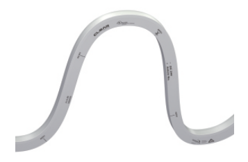
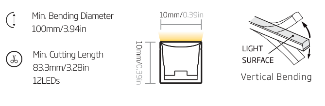
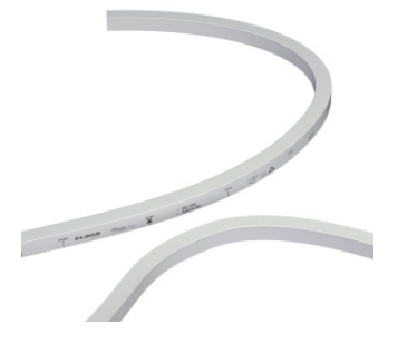
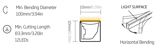
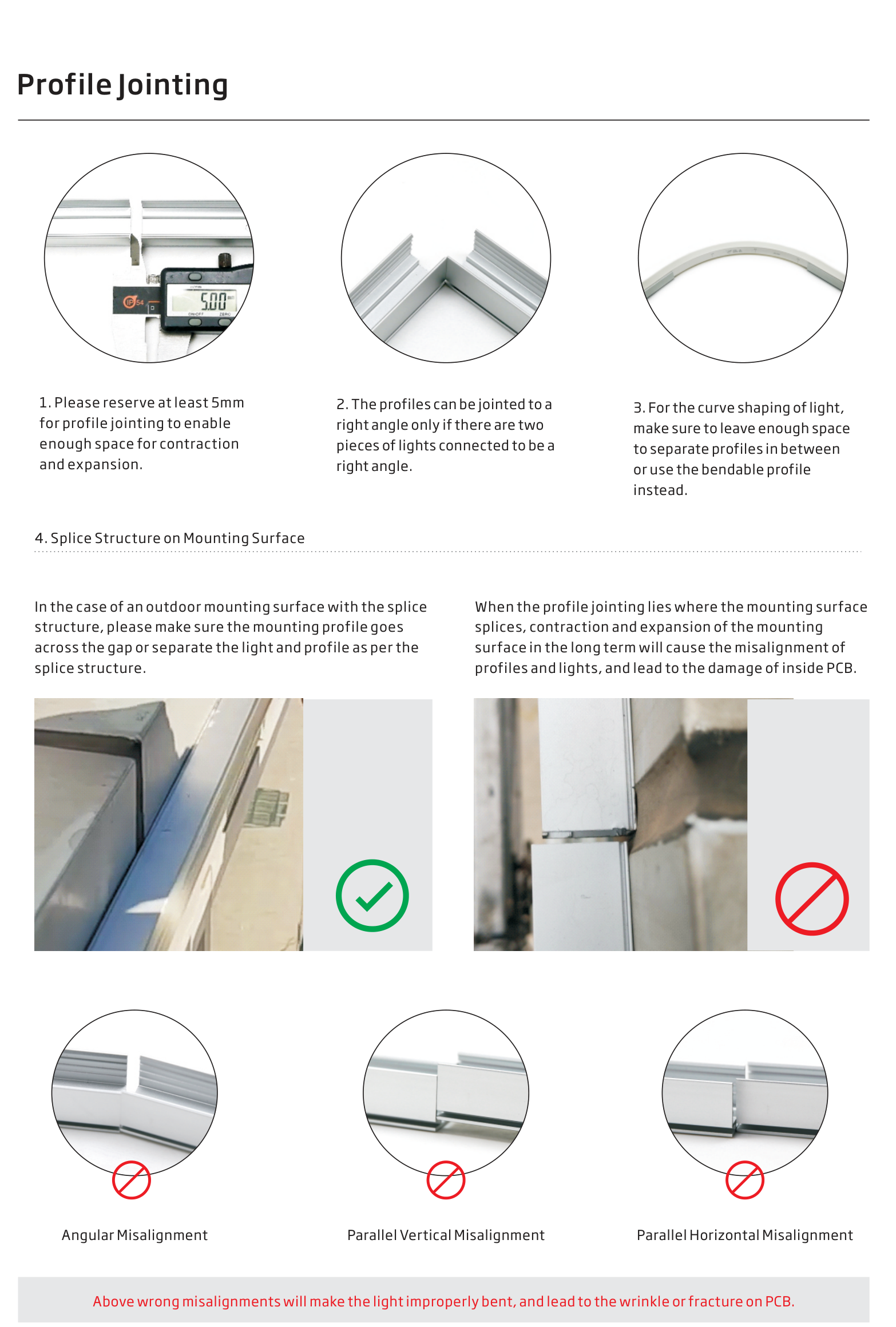
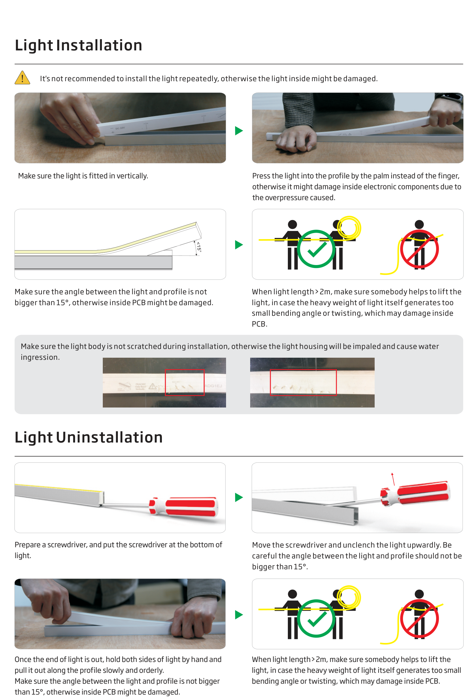
Two separate versions: select the bending direction before ordering. Minimum diameter Ø100 mm = radius R50 mm. Cut only at marked 83.3 mm intervals (12 LEDs). Do not twist the light or bend against its specified direction.
| Property | Specification |
|---|---|
| Material / light surface | Silicone / white body with milky diffuser |
| Supply / circuit | 24V DC, constant voltage |
| Cross-section | 10 × 10 mm |
| Power / current per metre | 4.5 W / 187.5 mA; 9 W / 375 mA |
| LEDs / cutting unit | 144 LEDs/m; 12 LEDs per 83.3 mm unit |
| Ingress protection | IP20 swivel; IP65 socket; IP67 factory-moulded silicone |
| White light / colour consistency | 2200 / 2700 / 3000 / 3500 / 4000 / 5700K; <5 SDCM |
| Colour rendering | CRI 80; CRI 90 at 2700–4000K; CRI 95 at 3000K |
| Working temperature | 4.5 W/m: −40 to +65°C; 9 W/m: −40 to +60°C |
| Storage / mounting surface | −40 to +60°C / max. +85°C when not operating |
| Dimming | PWM 100–2000 Hz; recommended 500 Hz |
| Supply length | Made to cutting units; electrical run limits and packaging limits apply |
IP protection applies to the assembled light including its connectors and end cap. Weight per metre and a fixed standard delivery length are not specified in the supplied technical data.
| Connector | IP | W/m | Single feed (m) | Double feed (m) | Load, single / double (W) |
|---|---|---|---|---|---|
| Silicone moulded | IP67 | 4.5 | 15 | 30 | 67.5 / 135 |
| Silicone moulded | IP67 | 9 | 7.5 | 15 | 67.5 / 135 |
| Socket | IP65 | 4.5 | 10 | 20 | 45 / 90 |
| Socket | IP65 | 9 | 5 | 10 | 45 / 90 |
| Swivel | IP20 | 4.5 | 10 | 20 | 45 / 90 |
| Swivel | IP20 | 9 | 5 | 10 | 45 / 90 |
Connected load is calculated as nominal W/m × maximum light length; it is not the power-supply rating. The source recommends at least 25% power-supply headroom. Run limits are based on a 0.3 m cable and full static load. Check cable length, conductor size and voltage drop for each project. Double feeding requires coordinated 24V feeds; do not parallel independent drivers without a suitable design. Electrical run length does not guarantee one-piece delivery length.
| Bend | Colour / CCT | CRI | W/m | lm/m | LEDPRO item code |
|---|---|---|---|---|---|
| VB | 2200K | 80 | 4.5 | 195 | NFS10-VB-24CV-22K-WM-144-80-4.5W-83.3 |
| VB | 2700K | 80 | 4.5 | 220 | NFS10-VB-24CV-27K-WM-144-80-4.5W-83.3 |
| VB | 3000K | 80 | 4.5 | 220 | NFS10-VB-24CV-30K-WM-144-80-4.5W-83.3 |
| VB | 3500K | 80 | 4.5 | 220 | NFS10-VB-24CV-35K-WM-144-80-4.5W-83.3 |
| VB | 4000K | 80 | 4.5 | 220 | NFS10-VB-24CV-40K-WM-144-80-4.5W-83.3 |
| VB | 5700K | 80 | 4.5 | 220 | NFS10-VB-24CV-57K-WM-144-80-4.5W-83.3 |
| VB | 2200K | 80 | 9 | 390 | NFS10-VB-24CV-22K-WM-144-80-9W-83.3 |
| VB | 2700K | 80 | 9 | 440 | NFS10-VB-24CV-27K-WM-144-80-9W-83.3 |
| VB | 3000K | 80 | 9 | 440 | NFS10-VB-24CV-30K-WM-144-80-9W-83.3 |
| VB | 3500K | 80 | 9 | 440 | NFS10-VB-24CV-35K-WM-144-80-9W-83.3 |
| VB | 4000K | 80 | 9 | 440 | NFS10-VB-24CV-40K-WM-144-80-9W-83.3 |
| VB | 5700K | 80 | 9 | 440 | NFS10-VB-24CV-57K-WM-144-80-9W-83.3 |
| VB | 2700K | 90 | 4.5 | 180 | NFS10-VB-24CV-27K-WM-144-90-4.5W-83.3 |
| VB | 3000K | 90 | 4.5 | 180 | NFS10-VB-24CV-30K-WM-144-90-4.5W-83.3 |
| VB | 3500K | 90 | 4.5 | 180 | NFS10-VB-24CV-35K-WM-144-90-4.5W-83.3 |
| VB | 4000K | 90 | 4.5 | 180 | NFS10-VB-24CV-40K-WM-144-90-4.5W-83.3 |
| VB | 3000K | 95 | 4.5 | 150 | NFS10-VB-24CV-30K-WM-144-95-4.5W-83.3 |
| VB | Red | — | 4.5 | 80 | NFS10-VB-24CV-R-WM-144-4.5W-83.3 |
| VB | Green | — | 4.5 | 220 | NFS10-VB-24CV-G-WM-144-4.5W-83.3 |
| VB | Blue | — | 4.5 | 50 | NFS10-VB-24CV-B-WM-144-4.5W-83.3 |
| VB | Amber | — | 4.5 | 80 | NFS10-VB-24CV-A-WM-144-4.5W-83.3 |
| HB | 2200K | 80 | 4.5 | 185 | NFS10-HB-24CV-22K-WM-144-80-4.5W-83.3 |
| HB | 2700K | 80 | 4.5 | 210 | NFS10-HB-24CV-27K-WM-144-80-4.5W-83.3 |
| HB | 3000K | 80 | 4.5 | 210 | NFS10-HB-24CV-30K-WM-144-80-4.5W-83.3 |
| HB | 3500K | 80 | 4.5 | 210 | NFS10-HB-24CV-35K-WM-144-80-4.5W-83.3 |
| HB | 4000K | 80 | 4.5 | 210 | NFS10-HB-24CV-40K-WM-144-80-4.5W-83.3 |
| HB | 5700K | 80 | 4.5 | 210 | NFS10-HB-24CV-57K-WM-144-80-4.5W-83.3 |
| HB | 2200K | 80 | 9 | 370 | NFS10-HB-24CV-22K-WM-144-80-9W-83.3 |
| HB | 2700K | 80 | 9 | 420 | NFS10-HB-24CV-27K-WM-144-80-9W-83.3 |
| HB | 3000K | 80 | 9 | 420 | NFS10-HB-24CV-30K-WM-144-80-9W-83.3 |
| HB | 3500K | 80 | 9 | 420 | NFS10-HB-24CV-35K-WM-144-80-9W-83.3 |
| HB | 4000K | 80 | 9 | 420 | NFS10-HB-24CV-40K-WM-144-80-9W-83.3 |
| HB | 5700K | 80 | 9 | 420 | NFS10-HB-24CV-57K-WM-144-80-9W-83.3 |
| HB | 2700K | 90 | 4.5 | 170 | NFS10-HB-24CV-27K-WM-144-90-4.5W-83.3 |
| HB | 3000K | 90 | 4.5 | 170 | NFS10-HB-24CV-30K-WM-144-90-4.5W-83.3 |
| HB | 3500K | 90 | 4.5 | 170 | NFS10-HB-24CV-35K-WM-144-90-4.5W-83.3 |
| HB | 4000K | 90 | 4.5 | 170 | NFS10-HB-24CV-40K-WM-144-90-4.5W-83.3 |
| HB | 3000K | 95 | 4.5 | 140 | NFS10-HB-24CV-30K-WM-144-95-4.5W-83.3 |
| HB | Red | — | 4.5 | 50 | NFS10-HB-24CV-R-WM-144-4.5W-83.3 |
| HB | Green | — | 4.5 | 200 | NFS10-HB-24CV-G-WM-144-4.5W-83.3 |
| HB | Blue | — | 4.5 | 30 | NFS10-HB-24CV-B-WM-144-4.5W-83.3 |
| HB | Amber | — | 4.5 | 50 | NFS10-HB-24CV-A-WM-144-4.5W-83.3 |
All configurations: 24V DC and 83.3 mm cutting units. Values are for the finished light. Single-colour versions are not RGB colour-changing products. R9: 35–80 for CRI 90; 80–99 for CRI 95. The 9 W/m white-light variants listed here are CRI 80.
| Image | Description | LEDPRO code |
|---|---|---|
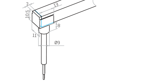
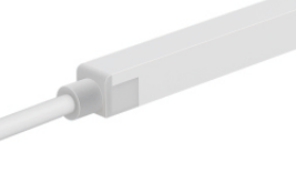 | Factory-moulded end feed IP67; 0.3 / 1 / 3 / 5 / 10 / 15 / 20 m cable | NFS10-{HB/VB}-SIM/FC-01/02-E |
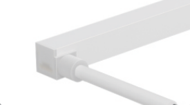 | Factory-moulded side feed IP67; HB: 02-SL or 01-SR; VB: 01/02-SL/SR. Same cable options as end feed. | NFS10-{HB/VB}-SIM/FC-…-SL/SR |
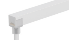 | Factory-moulded bottom feed IP67; same cable options as end feed | NFS10-{HB/VB}-SIM/FC-01/02-B |
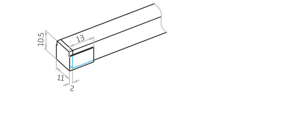
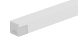 | Factory-moulded end cap IP67 termination; supplied as part of the manufactured light | NFS10-SIM/EC |
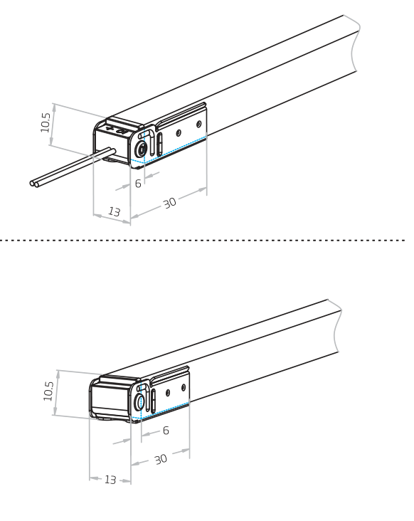
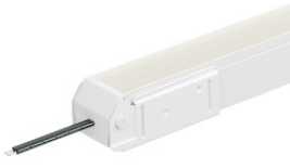 | Swivel end feed + end cap IP20; on-site assembly; 0.3 / 1 m cable | NFS10-{HB/VB}-SW/FC-01/02-E NFS10-SW/EC |
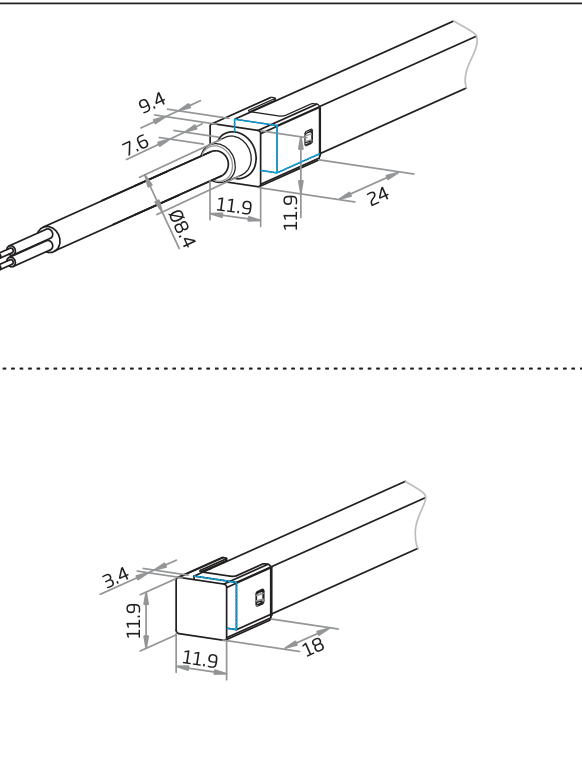
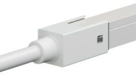 | Socket end feed + end cap IP65; on-site assembly; 0.3 / 1 / 3 / 5 m cable | NFS10-{HB/VB}-SO/FC-01/02-E NFS10-SO/EC |
Factory-moulded connections and end caps are manufacturing options, not loose field-installable accessories. Specify direction, feed position and cable length when ordering. Factory-moulded jumpers (0.3 / 1 m) and middle power T-feeds (0.3 / 1 / 3 m) are also listed: NFS10-{HB/VB}-SIM/JU and NFS10-{HB/VB}-SIM/MC-PTF.
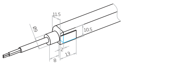
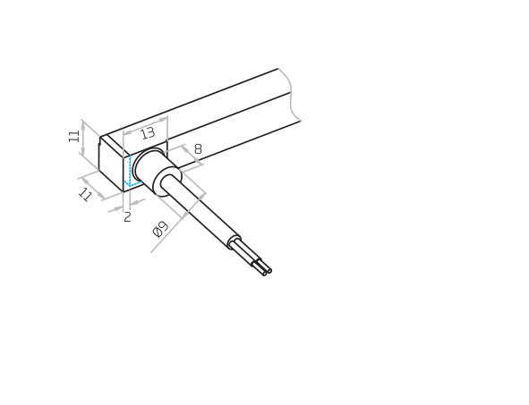
| Image | Profile | Code family | Lengths (mm) |
|---|---|---|---|
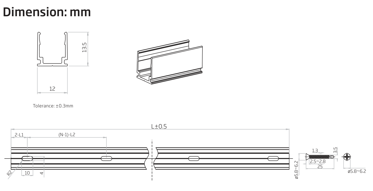
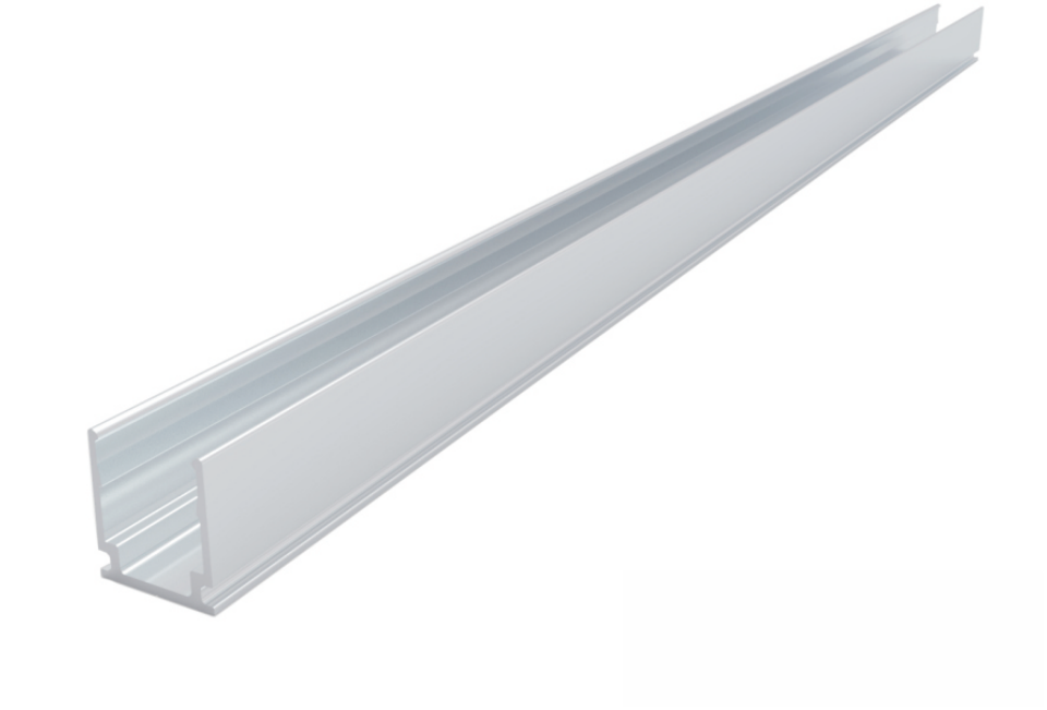 | Aluminum profile Outer section: 12 × 13.5 mm | NFS10-A/PL | 35 / 500 / 1000 / 2000 |
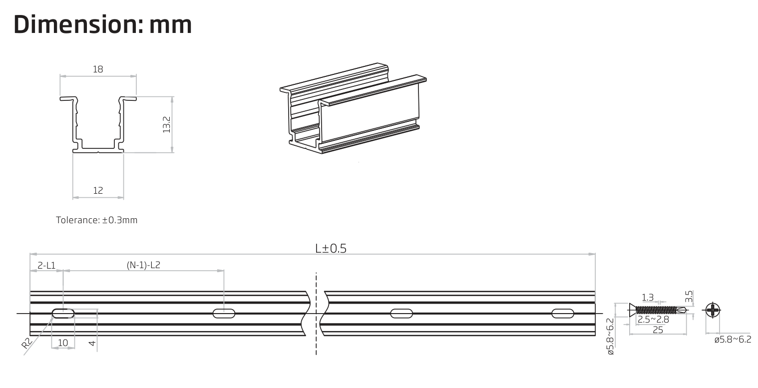
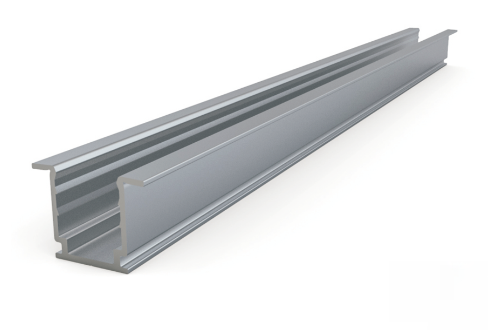 | Flange aluminum profile Outer section: 18 × 13.2 mm | NFS10-FA/PL | 35 / 500 / 1000 / 2000 |
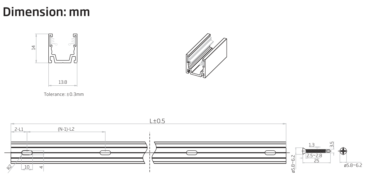
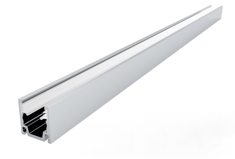 | Serrated aluminum profile Outer section: 13.8 × 14 mm | NFS10-SA/PL | 20 / 500 / 1000 / 2000 |
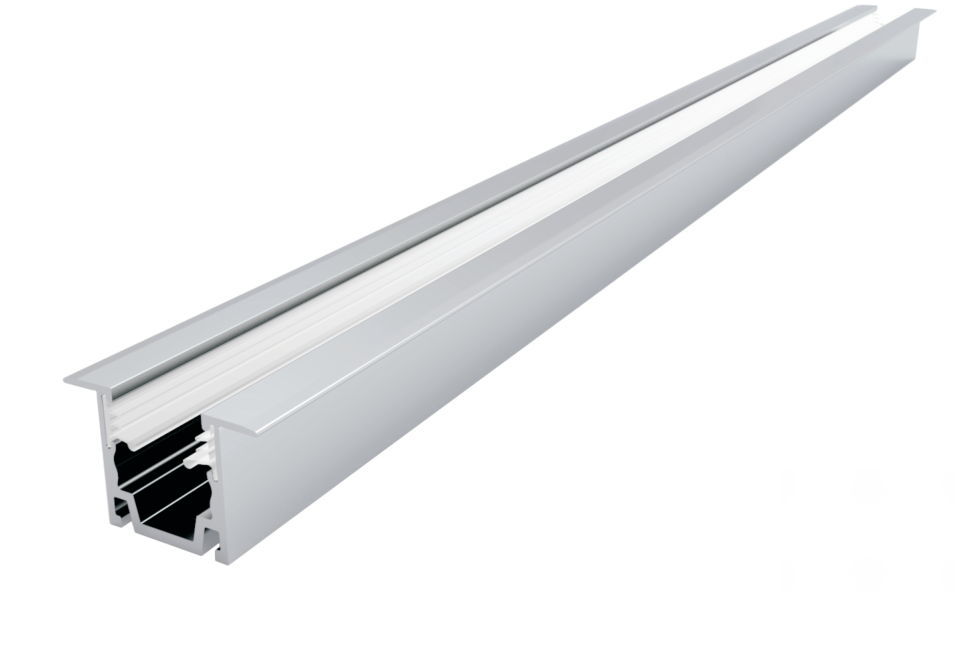 | Flange serrated aluminum profile Outer section: 21.8 × 14 mm | NFS10-FSA/PL | 20 / 500 / 1000 / 2000 |
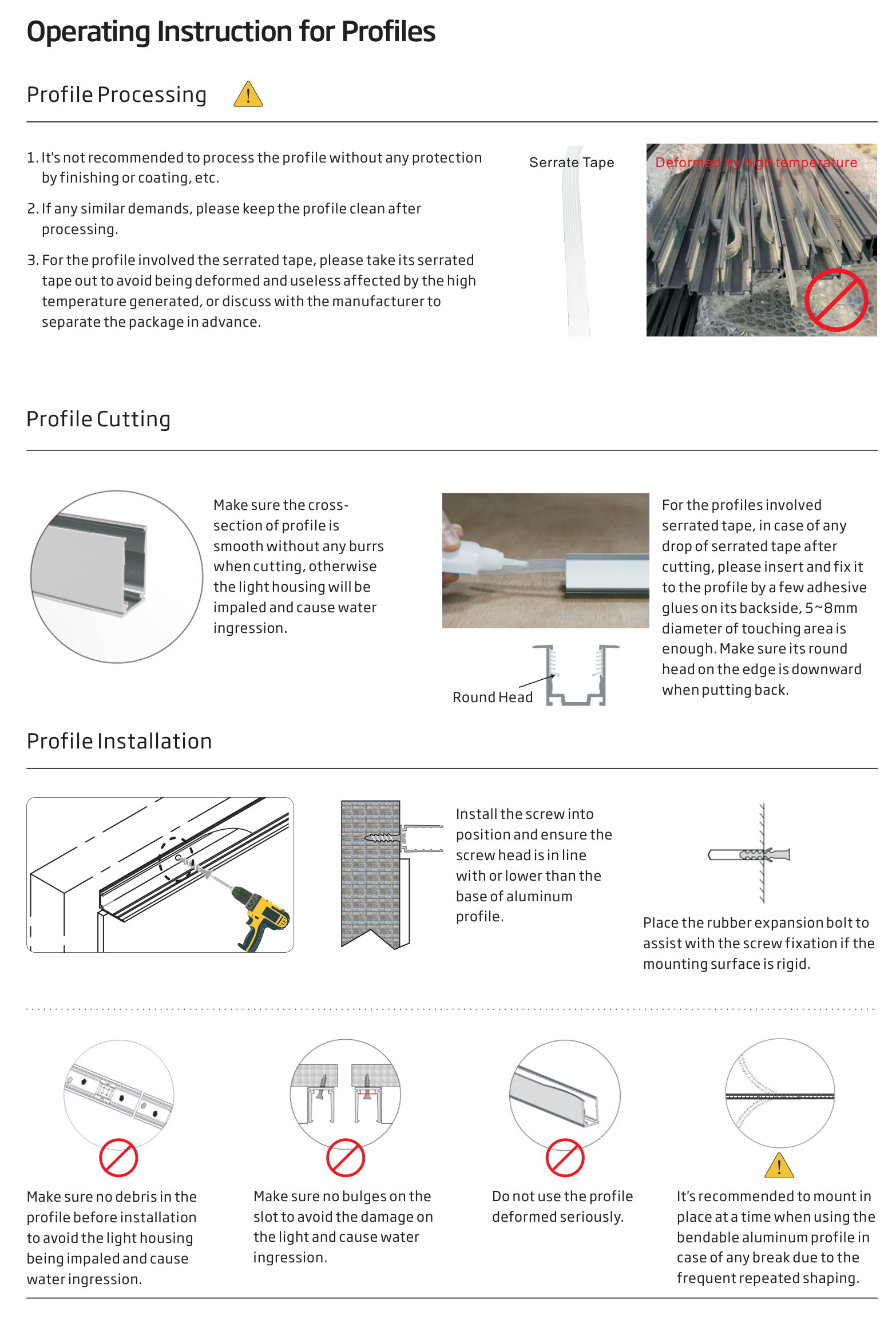
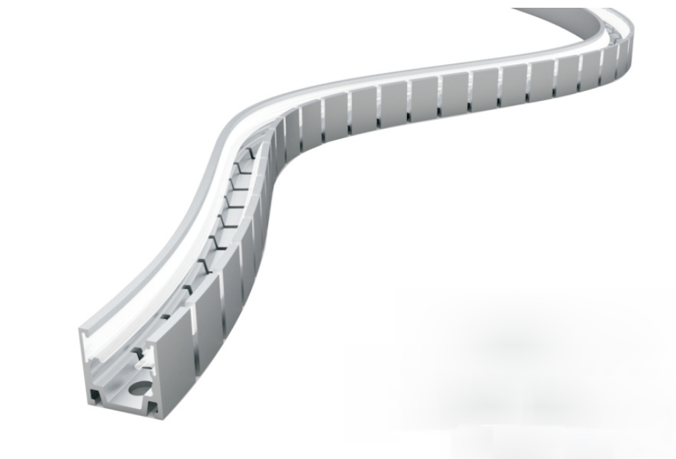 | Bendable serrated aluminum profile Outer section: 13.8 × 14 mm | NFS10-BSA/PL | 500 / 1000 |
Bendable profiles are for horizontal curves only. Minimum profile bending diameter: 100 mm with the toothed side outwards; 200 mm with the toothed side inwards. The light’s own bending limits also apply.
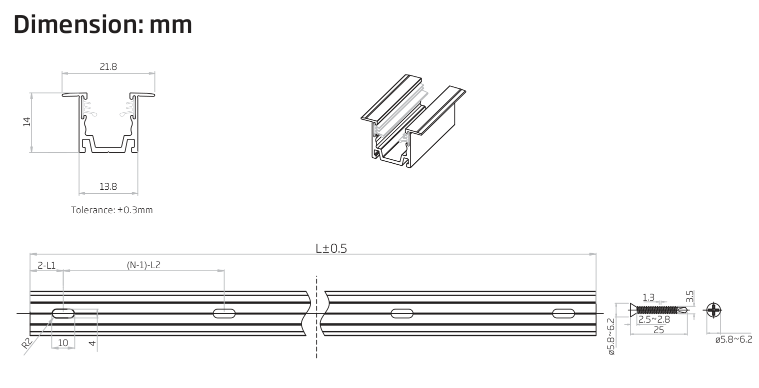
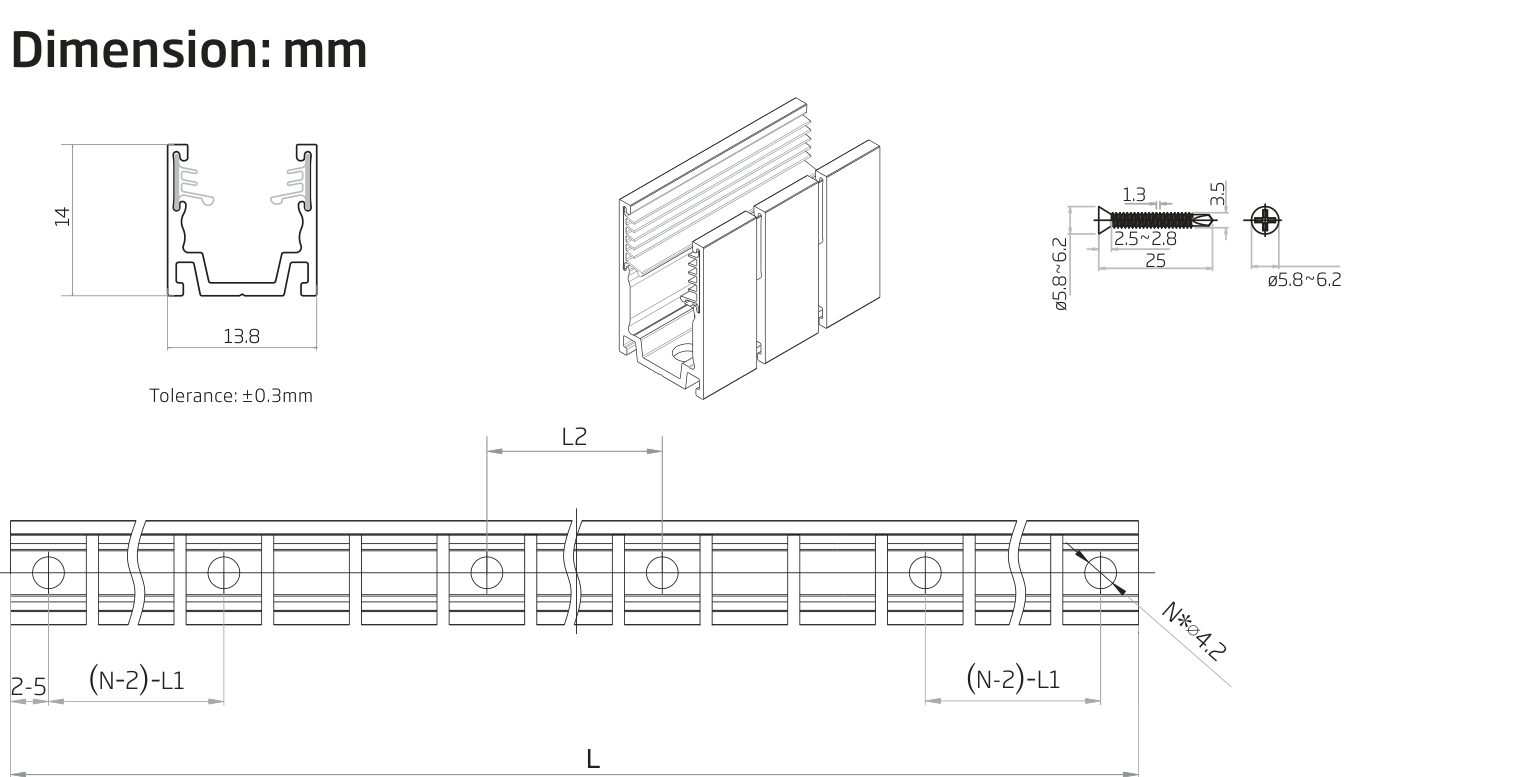
| Image | Description | Code |
|---|---|---|
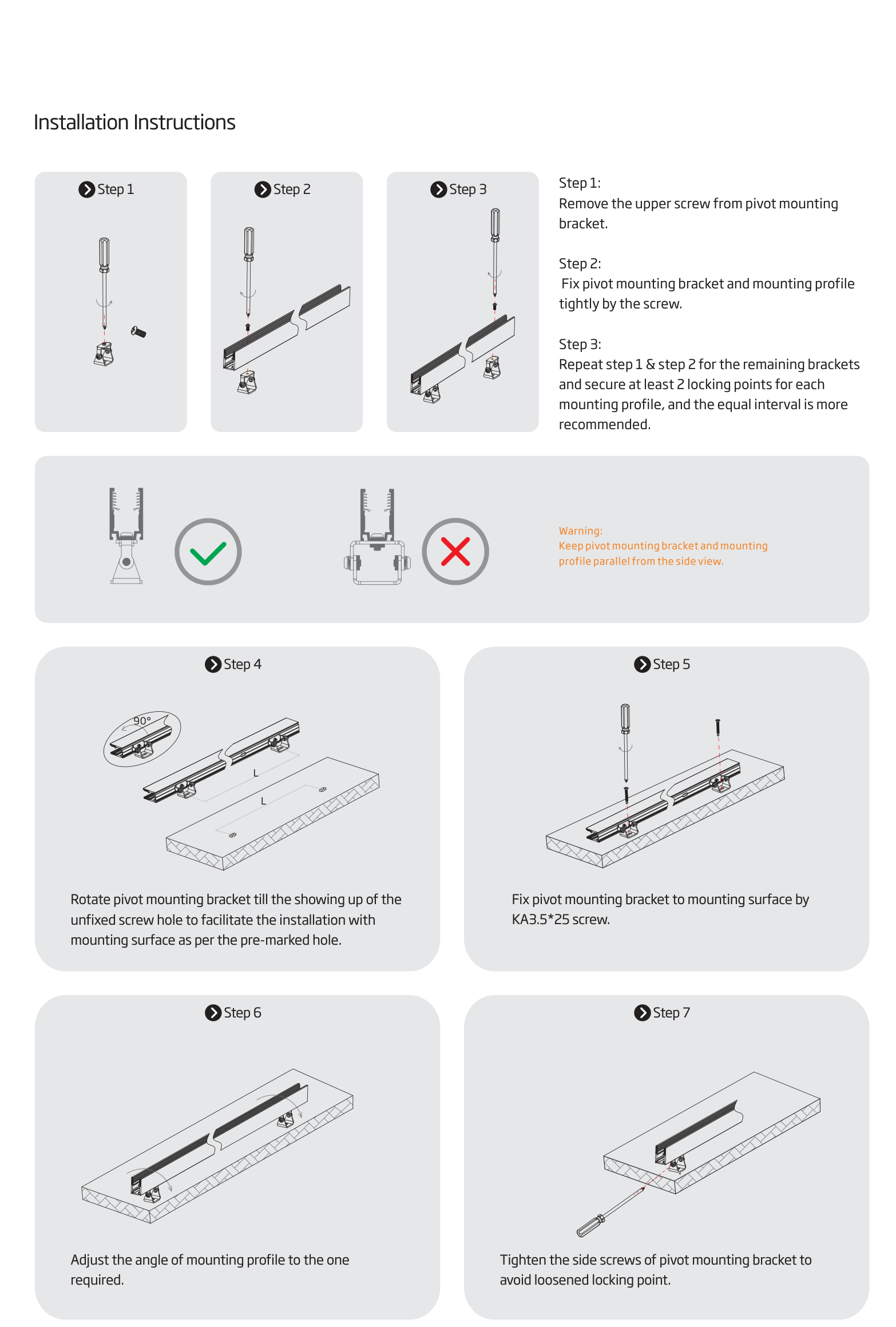
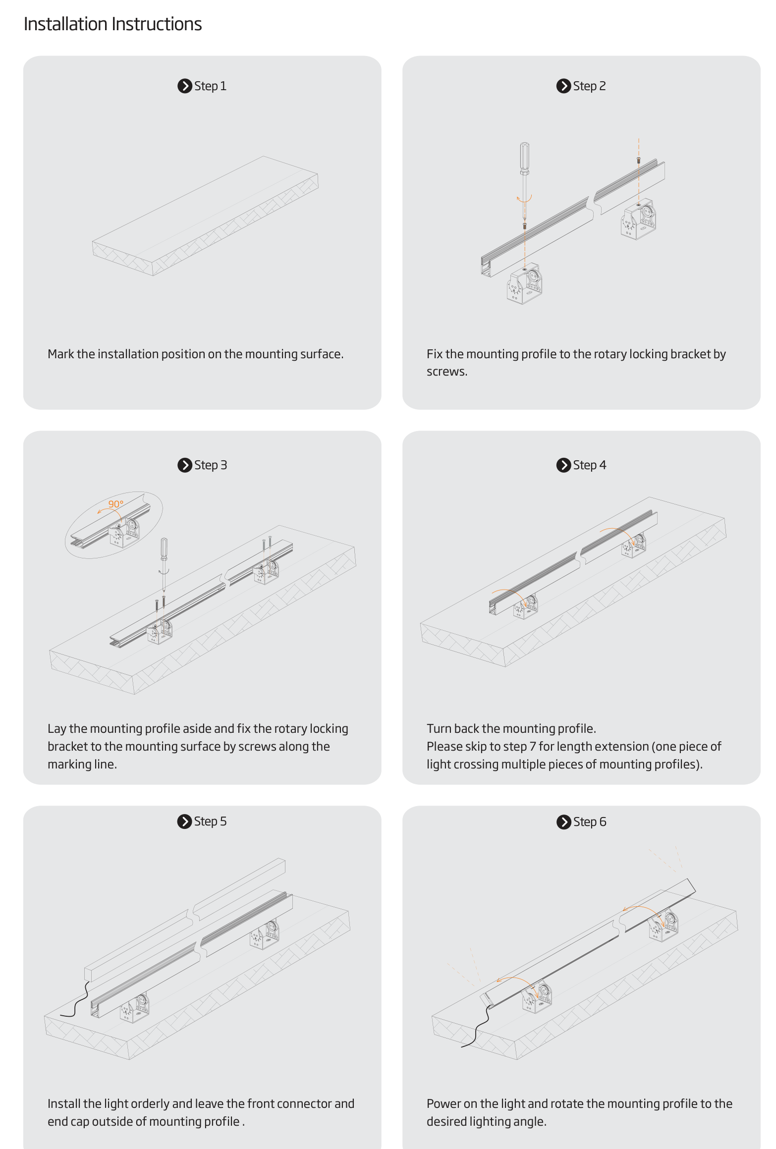
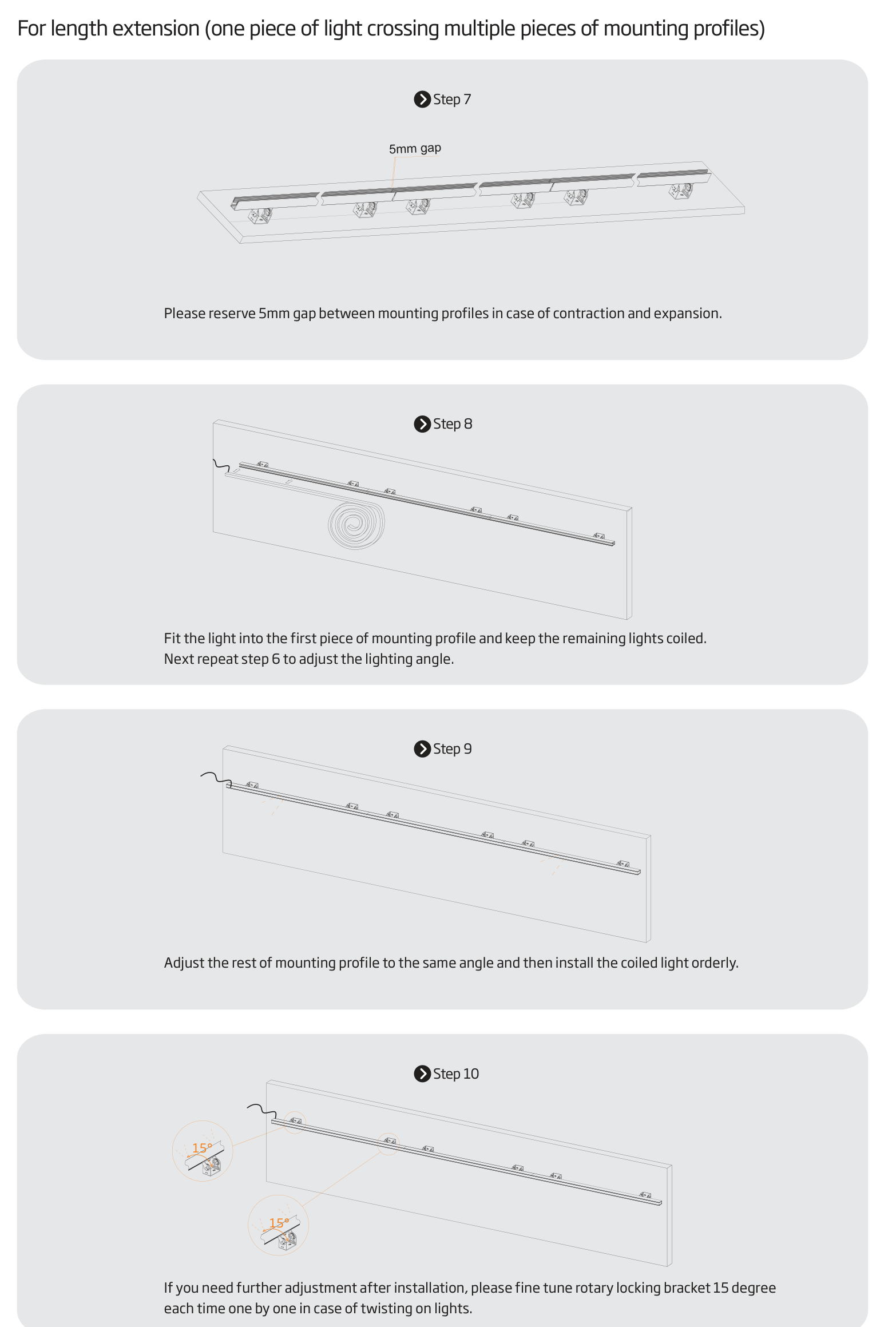
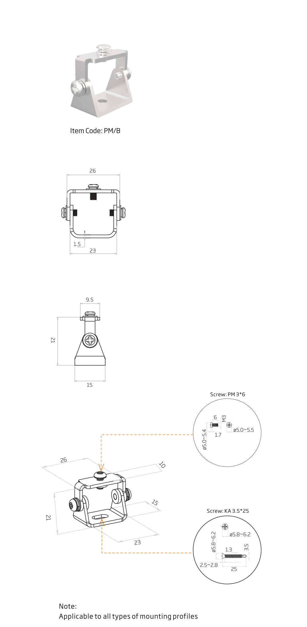 | Pivot mounting bracket Adjustable mounting; at least two locking points per profile. | PM/B |
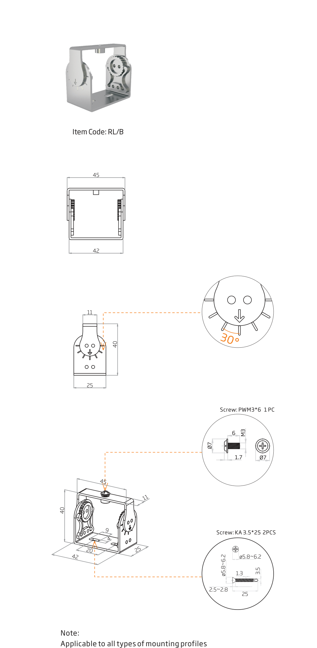 | Rotary locking bracket Angle adjustment; keep adjacent profiles aligned. | RL/B |
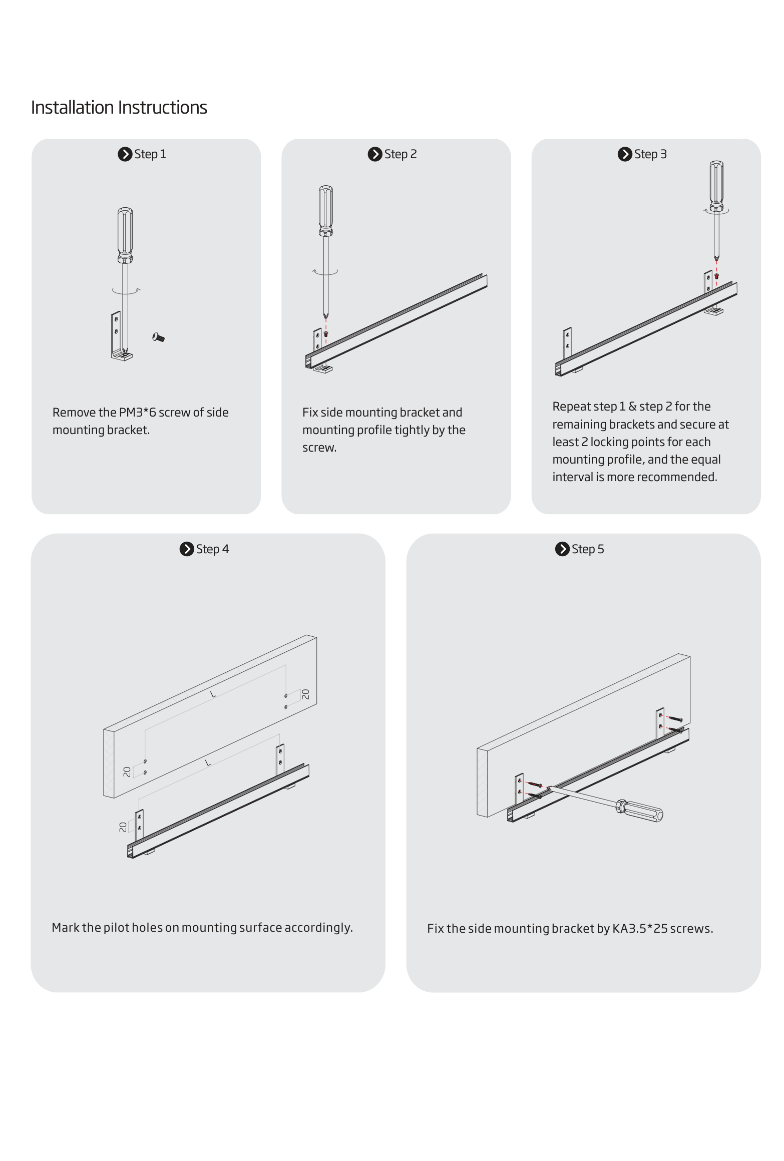
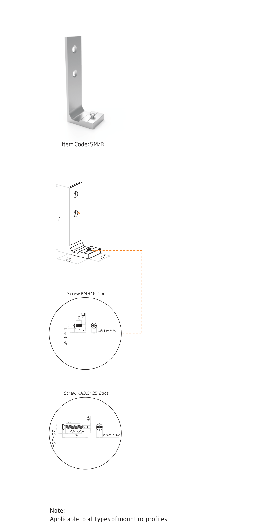 | Side mounting bracket Side mounting; at least two locking points per profile. | SM/B |
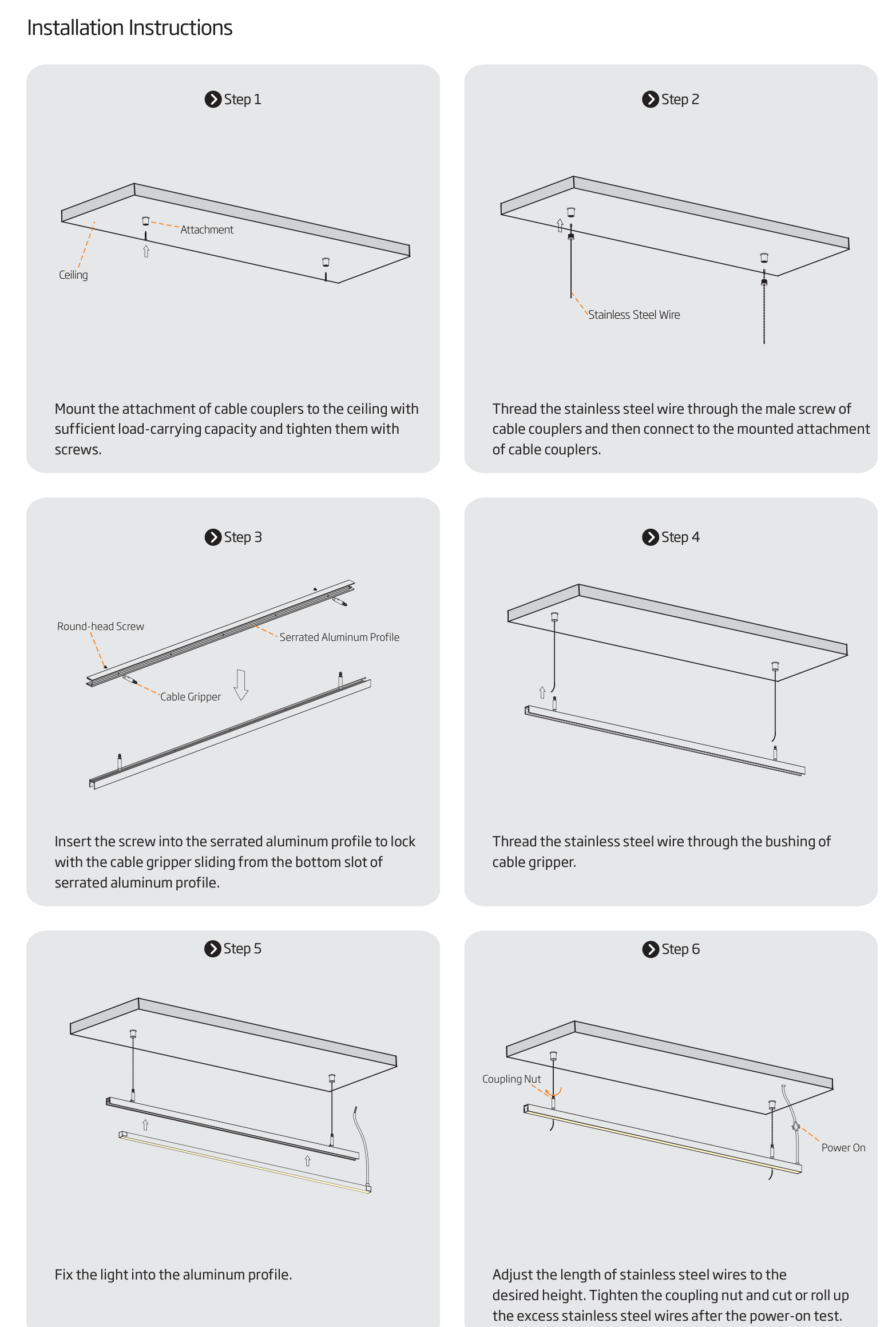
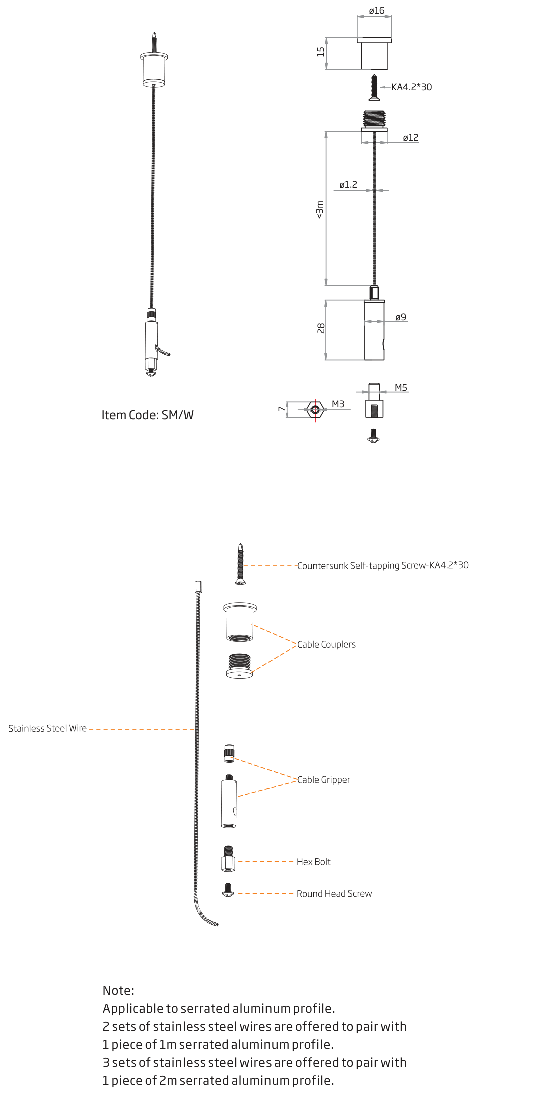 | Suspended mounting wire For serrated profiles; 2 sets per 1 m profile, 3 sets per 2 m profile. | SM/W |
Cable-exit mounting clips for moulded side and bottom feeds: NFS10-SA/PL-SL, NFS10-SA/PL-SR and NFS10-SA/PL-B. Length: 100 mm.
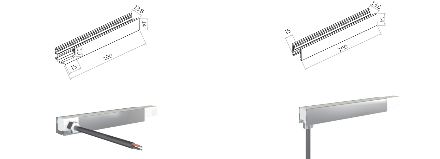
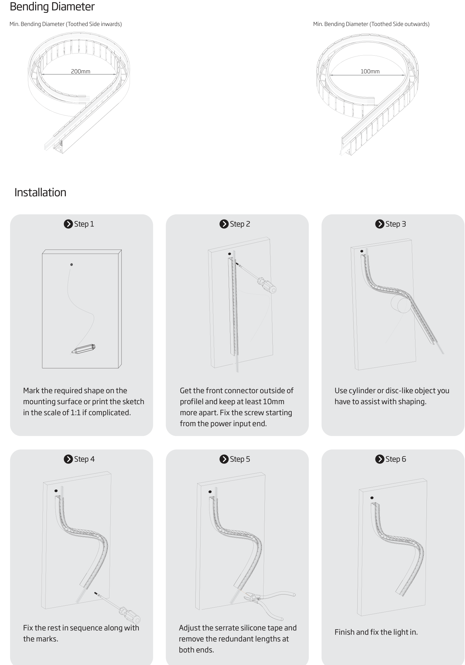
Send your required lengths, bending direction, light colour, mounting method and cable positions.
Contact LEDPRO